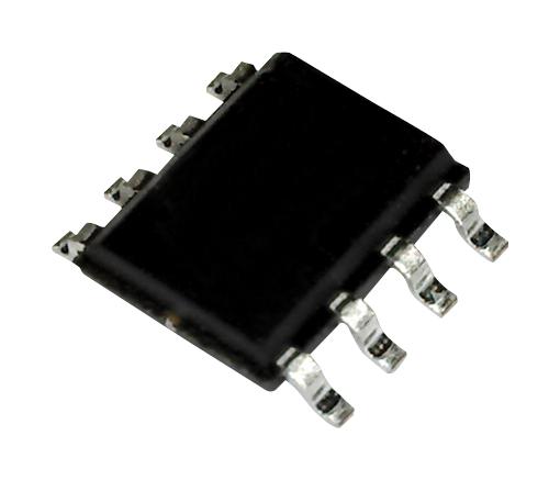
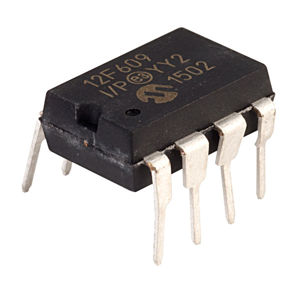
Unlock Secured PIC12F609 MCU Flash Heximal
Unlock Secured PIC12F609 MCU Flash Heximal and copy embedded firmware from original pic12f609 to new microcontroller, the protection system over pic12f609 will be break off;

Figure 18-1 shows a possible application voltage curve (typically for batteries). Over time, the device voltage decreases. When the device voltage equals voltage VA, the LVD logic generates an interrupt. This occurs at time TA.

The application software then has the time, until the device voltage is no longer in valid operating range, to shut down the system to unlock pic12f609 microcontroller security fuse bit. Voltage point VB is the minimum valid operating voltage specification. This occurs at time TB. The difference, TB – TA, is the total time for shutdown.
The block diagram for the LVD module is shown in Figure 18-2 (following page). A comparator uses an internally generated reference voltage as the set point. When the selected tap output of the device voltage crosses the set point (is lower than), the LVDIF bit is set.

Each node in the resistor divider represents a “trip point” voltage. The “trip point” voltage is the minimum supply voltage level at which the device can operate before the LVD module asserts an interrupt. When the supply voltage is equal to the trip point to extract source code from pic16f747 microcontroller, the voltage tapped off of the resistor array is equal to the 1.2V internal reference voltage generated by the voltage reference module.
The comparator then generates an interrupt signal setting the LVDIF bit. This voltage is software programmable to any one of 16 values (see Figure 18-2). The trip point is selected by programming the LVDL3:LVDL0 bits (LVDCON<3:0>).

