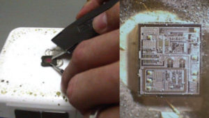
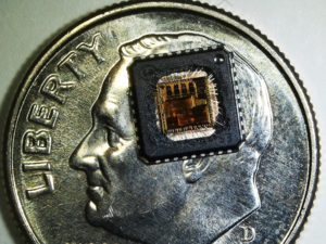
Unlock PIC18F2450 Microcontroller Protected Flash
Unlock PIC18F2450 Microcontroller Protected Flash and eeprom memory such as the program and data, then copy the firmware to other blank Microcontroller;
Devices in the PIC18F2450 family are available in 28-pin and 40/44-pin packages. Block diagrams for the two groups are shown in Figure 1-1 and Fgure 1-2.
The devices are differentiated from each other in five ways:Flash program memory (16 Kbytes for PIC18F2450 devices and 32 Kbytes for PIC18F2450).
A/D channels (10 for 28-pin devices, 13 for 40/44-pin devices).
I/O ports (3 bidirectional ports on 28-pin devices, 5 bidirectional ports on 40/44-pin devices).
CCP and Enhanced CCP implementation (28-pin devices have 2 standard CCP modules, 40/44-pin devices have one standard CCP module and one ECCP module).
Parallel Slave Port (present only on 40/44-pin devices). All other features for devices in this family are identical. These are summarized in Table 1-1. The pinouts for all devices are listed in Table 1-2 and Table 1-3.
Like all Microchip PIC18 devices, members of the PIC18F2450 family are available as both standard and low-voltage devices. Standard devices with Enhanced Flash memory, designated with an “F” in the part number (such as PIC18F2450), accommodate an operating VDD range of 4.2V to 5.5V.
Low-voltage parts, designated by “LF” (such as PIC18F2450), function over an extended VDD range of 2.0V to 5.5V.
In XT, LP, HS or HSPLL Oscillator modes, a crystal or ceramic resonator is connected to the OSC1 and OSC2 pins to establish oscillation. Figure 2-1 shows the pin connections. The oscillator design requires the use of a parallel cut crystal.
Different capacitor values may be required to produce acceptable oscillator operation. The user should test the performance of the oscillator over the expected VDD and temperature range for the application. When using resonators with frequencies above 3.5 MHz, the use of HS mode, rather than XT mode, is recommended.
HS mode may be used at any VDD for which the controller is rated. If HS is selected, it is possible that the gain of the oscillator will overdrive the resonator. Therefore, a series resistor should be placed between the OSC2 pin and the resonator. As a good starting point, the recommended value of RS is 330Ω.


