Unlock NXP MCU P89LPC915 Protected Flash
Through signal manipulation on the MCU core processor it will disable the content transmission sequence and get the Unlock NXP MCU P89LPC915 Protected Flash complete.
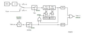
This bit can be used to generate an interrupt (by enabling the Timer 2 interrupt bit in the IEN0 register). If EXEN2 = 1, Timer 2 operates as described above, but with the added feature that a 1- to -0 transition at external input T2EX causes the current value in the Timer 2 registers, TL2 and TH2, to be captured into registers RCAP2L and RCAP2H, respectively.
In addition, the transition at T2EX causes bit EXF2 in T2CON to be set, and EXF2 like TF2 can generate an interrupt (which vectors to the same location as Timer 2 overflow interrupt).

Unlock NXP MCU P89LPC915 Protected Flash
The Timer 2 interrupt service routine can interrogate TF2 and EXF2 to determine which event caused the interrupt.
There is no reload value for TL2 and TH2 in this mode.
Even when a capture event occurs from T2EX, the counter keeps on counting T2 pin transitions or fosc/6 pulses. Since once loaded contents of RCAP2L and RCAP2H registers are not protected to facilitate the process of Philip Chip LPC87LPC761 Heximal Code cloning, once Timer2 interrupt is signalled it has to be serviced before new capture event on T2EX pin occurs.
Otherwise, the next falling edge on T2EX pin will initiate reload of the current value from TL2 and TH2 to RCAP2L and RCAP2H and consequently corrupt their content related to previously reported interrupt.
In the 16-bit auto-reload mode, Timer 2 can be configured as either a timer or counter (via C/T2 in T2CON), then programmed to count up or down. The counting direction is determined by bit DCEN (Down Counter Enable) which is located in the T2MOD register (see below Table).
When reset is applied, DCEN = 0 and Timer 2 will default to counting up. If the DCEN bit is set, Timer 2 can count up or down depending on the value of the T2EX pin.
Figure 13 shows Timer 2 counting up automatically (DCEN = 0).


