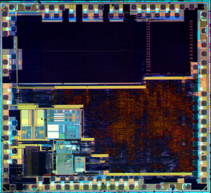
Unlock Microcontroller ATtiny2313A Software
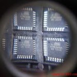
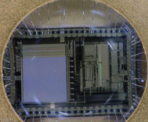
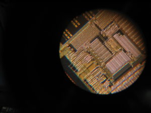
Unlock Microcontroller ATtiny2313A and readout the Software from its memory include flash and eeprom, the security fuse bits of the MCU can be located and disable by using IC breaking technique:
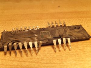
Unlock Microcontroller ATtiny2313A and readout the Software from its memory include flash and eeprom, the security fuse bits of the MCU
Reading EEPROM at low frequency may not work for frequencies below 900 kHz
1. Reading EEPROM at low frequency may not work for frequencies below 900 kHz Reading data from the EEPROM at low internal clock frequency may result in wrong data read.
Problem Fix/Workaround
Avoid using the EEPROM at clock frequency below 900kHz. PLL not locking
EEPROM read from application code does not work in Lock Bit Mode 3
Reading EEPROM at low frequency may not work for frequencies below 900 kHz
Timer Counter 1 PWM output generation on OC1B- XOC1B does not work correctly
1. PLL not locking
When at frequencies below 6.0 MHz, the PLL will not lock
Problem fix / Workaround When using the PLL, run at 6.0 MHz or higher.
2. EEPROM read from application code does not work in Lock Bit Mode 3 after crack PIC18F25K20 firmware
When the Memory Lock Bits LB2 and LB1 are programmed to mode 3, EEPROM read does not work from the application code.
Problem Fix/Work around
Do not set Lock Bit Protection Mode 3 when the application code needs to read from EEPROM.
3. Reading EEPROM at low frequency may not work for frequencies below 900 kHz
Reading data from the EEPROM at low internal clock frequency may result in wrong data read.
Problem Fix/Workaround
Avoid using the EEPROM at clock frequency below 900kHz
4. Timer Counter 1 PWM output generation on OC1B – XOC1B does not work correctly
Timer Counter1 PWM output OC1B-XOC1B does not work correctly. Only in the case when the control bits, COM1B1 and COM1B0 are in the same mode as COM1A1 and COM1A0, respectively, the OC1B-XOC1B output works correctly.
Problem Fix/Work around
The only workaround is to use same control setting on COM1A(1:0) and COM1B(1:0) control bits, see table 14-4 in the data sheet. The problem has been fixed for Tiny45 rev D after Unlock Microcontroller.
Tags: unlock microcontroller flash archive,unlock microcontroller flash binary,unlock microcontroller flash code,unlock microcontroller flash content,unlock microcontroller flash data,unlock microcontroller flash eeprom,unlock microcontroller flash file,unlock microcontroller flash firmware,unlock microcontroller flash heximal,unlock microcontroller flash information,unlock microcontroller flash memory,unlock microcontroller flash program


