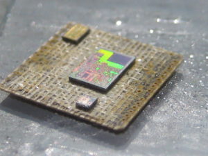
Secured Chip PIC18F2515 Flash Unlock
Secured chip PIC18F2515 Flash Unlock can help to remove the protection over its memory like flash and eeprom, readout the firmware from its memory cell:
Enabling any on-chip feature that will operate during Sleep will increase the current consumed during Sleep. The INTRC is required to support WDT operation. The Timer1 oscillator may be operating to support a real-time clock. Other features may be operating that do not require a device clock source (i.e., SSP slave, PSP, INTn pins and others). Peripherals that may add significant current consumption are listed in Section 26.2 “DC Characteristics”.
Power-up delays are controlled by two timers, so that no external Reset circuitry is required for most applications. The delays ensure that the device is kept in Reset until the device power supply is stable under normal circumstances and the primary clock is operating and stable. For additional information on power-up delays, see Section 4.5 “Device Reset Timers”.
The first timer is the Power-up Timer (PWRT), which provides a fixed delay on power-up (parameter 33, Table 26-10). It is enabled by clearing (= 0) the PWRTEN configuration bit. The second timer is the Oscillator Start-up Timer (OST), intended to keep the chip in Reset until the crystal oscillator is stable (LP, XT and HS modes). The OST does this by counting 1024 oscillator cycles before allowing the oscillator to clock the device.
When the HSPLL Oscillator mode is selected, the device is kept in Reset for an additional 2 ms, following the HS mode OST delay, so the PLL can lock to the incoming clock frequency. There is a delay of interval TCSD (parameter 38, Table 26-10), following POR, while the controller becomes ready to execute instructions. This delay runs concurrently with any other delays. This may be the only delay that occurs when any of the EC, RC or INTIO modes are used as the primary clock source.
PIC18F2515 devices offer a total of seven operating modes for more efficient power management. These modes provide a variety of options for selective power conservation in applications where resources may be limited (i.e., battery-powered devices). There are three categories of power managed modes before the MCU’s binary has been unlocked:
Run modes
Idle modes
Sleep mode
These categories define which portions of the device are clocked and sometimes, what speed. The Run and Idle modes may use any of the three available clock sources (primary, secondary or internal oscillator block); the Sleep mode does not use a clock source. The power managed modes include several power-saving features offered on previous PICmicro® devices. One is the clock switching feature, offered in other PIC18 devices, allowing the controller to use the Timer1 oscillator in place of the primary oscillator. Also included is the Sleep mode, offered by all PICmicro devices, where all device clocks are stopped.


