Retrieve PIC MCU Microchip PIC18F2520
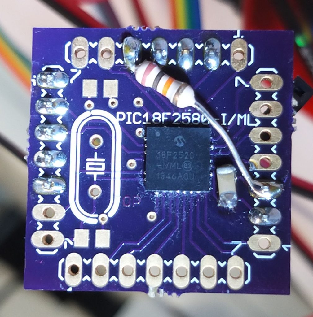
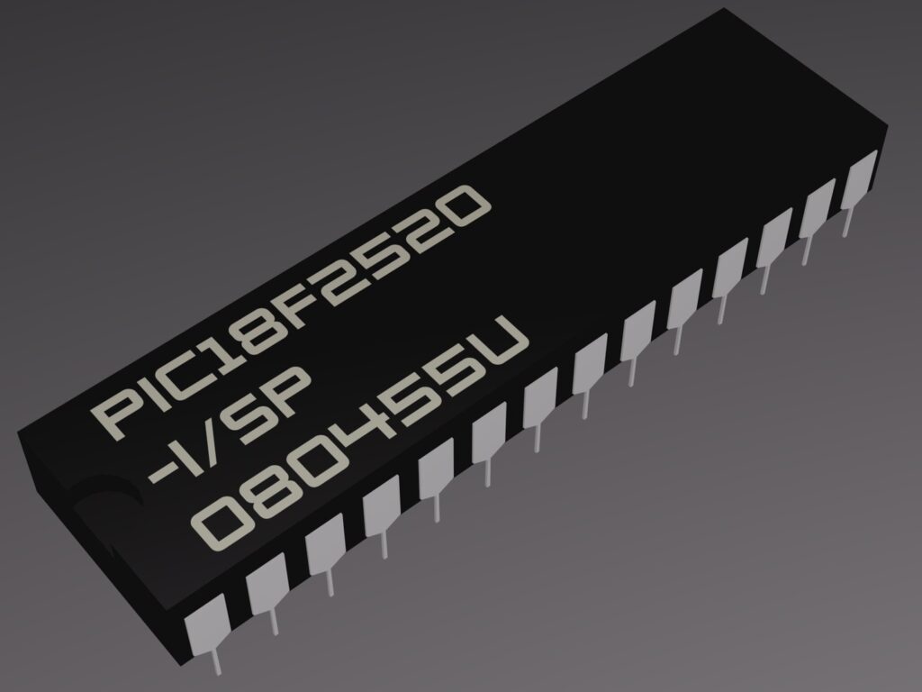
The Microchip PIC18F2520 is a powerful and widely adopted 8-bit microcontroller (MCU) known for its high performance, integrated peripherals, and reliability in a wide range of embedded system applications. It is commonly used in automotive, industrial, consumer electronics, and control systems. As with many modern microcontroller chips, the PIC18F2520 includes security features designed to protect proprietary firmware, binary files, and source code stored in its internal EEPROM and flash memory. However, there are legitimate scenarios where it becomes necessary to retrieve the content of a locked PIC18F2520 MCU.

Situations such as system recovery, legacy code support, or the need to analyze device behavior often require engineers to extract or read out the original program and data archives stored in the MCU. When the original heximal files or firmware backups are unavailable, attempts to retrieve this information may involve reverse engineering, replication, or even cloning the device to preserve or replicate the functionality.
Security Features and Challenges
The PIC18F2520 includes multiple layers of protection designed to prevent unauthorized access to its internal memory. These include code protection bits that disable external readout, locked debugging interfaces, and sometimes encrypted storage mechanisms. These protections help safeguard intellectual property and make it highly difficult for attackers to crack, hack, or decrypt the MCU content.

Breaking these protections is not straightforward. Engineers attempting to unlock or duplicate the device must deal with:
- Protected Memory Regions – Both the EEPROM and flash memory areas are usually secured, preventing direct readout using standard programming tools.
- Disabled Interfaces – Once protection bits are set, interfaces like ICSP (In-Circuit Serial Programming) may be limited or fully disabled.
- Tamper Responses – Some MCUs are designed to erase data when unauthorized access or attack is detected, making data retrieval risky.
- Complex Code Structures – Even if a partial dump is achieved, decoding, decrypting, and reconstructing the source code from raw binary is highly complex and often imprecise without symbolic information.

Retrieve PIC MCU Microchip 18F2520 embedded firmware from its memory which include the flash and eeprom area, please view below chip features for your reference:
one with Auto-Shutdown (28-pin devices)
· Enhanced Capture/Compare/PWM (ECCP)
module (40/44-pin devices only):
– One, two or four PWM outputs
– Selectable polarity
– Programmable dead time
– Auto-shutdown and auto-restart
· Single-Supply 5V In-Circuit Serial
Programming™ (ICSP™) via Two Pins
· In-Circuit Debug (ICD) via Two Pins
· Wide Operating Voltage Range: 2.0V to 5.5V
· Programmable Brown-out Reset (BOR) with
Software Enable Option


