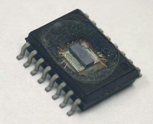
Retrieve NXP P89LPC924 Microprocessor Eeprom Binary
Except Mode 1 on the UART, Mode 2 & 3 are also critical for Retrieve NXP P89LPC924 Microprocessor Eeprom Binary, Reception is performed in the same manner as in mode 1. The signal to load SBUF and RB8, and to set RI, will be generated if, and only if, the following conditions are met at the time the final shift pulse is generated: (a) RI = 0, and (b) Either SM2 = 0, or the received 9th data bit = 1.
If either of these conditions is not met, the received frame is irretrievably lost, and RI is not set. If both conditions are met, the received 9th data bit goes into RB8, and the first 8 data bits go into SBUF.
UART modes 2 and 3 have a special provision for multiprocessor communications. In these modes, 9 data bits are received or transmitted. When data is received, the 9th bit is stored in RB8. The UART can be programmed so that when the stop bit is received, the serial port interrupt will be activated only if RB8 = 1 in the process of NXP MCU P89LPC912 Binary Unlocking.
This feature is enabled by setting bit SM2 in SCON. One way to use this feature in multiprocessor systems is as follows:
When the master processor wants to transmit a block of data to one of several slaves, it first sends out an address byte which identifies the target slave. An address byte differs from a data byte in a way that the 9th bit is ‘1’ in an address byte and ‘0’ in the data byte.
With SM2 = 1, no slave will be interrupted by a data byte, i.e. the received 9th bit is ‘0’. However, an address byte having the 9th bit set to ‘1’ will interrupt all slaves, so that each slave can examine the received byte and see if it is being addressed or not.
The addressed slave will clear its SM2 bit and prepare to receive the data (still 9 bits long) that follow. The slaves that weren’t being addressed leave their SM2 bits set and go on about their business, ignoring the subsequent data bytes.
SM2 has no effect in Mode 0, and in Mode 1 can be used to check the validity of the stop bit, although this is better done with the Framing Error flag. When UART receives data in mode 1 and SM2 = 1, the receive interrupt will not be activated unless a valid stop bit is received.


