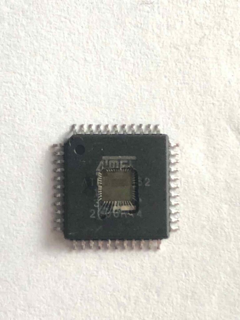
Replicate ATMEGA6490-16AUR AVR MCU Program
Replicate ATMEGA6490-16AUR AVR MCU Program from flash memory and eeprom memory, reverse engineering atmega6490 microcontroller tamper resistance system, and then readout embedded firmware from atmega64 avr microprocessor;

Many register and bit references in this document are written in general form. A lower case “n” replaces the Timer/Counter number, in this case 0. However, when using the register or bit defines in a program, the precise form must be used i.e. TCNT0 for accessing Timer/Counter0 counter value and so on.
The Timer/Counter can be clocked by an internal or an external clock source. The clock source is selected by the clock select logic which is controlled by the clock select (CS02:0) bits located in the Timer/Counter Control Register (TCCR0) when crack mcu atmega2561 flash memory protection. For details on clock sources and prescaler.

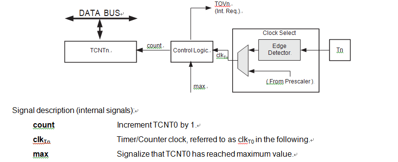
The main part of the 8-bit Timer/Counter is the programmable counter unit. Figure 15-2 shows a block diagram of the counter and its surroundings.

The counter is incremented at each timer clock (clkT0). clkT0 can be generated from an external or internal clock source, selected by the clock select bits (CS02:0). When no clock source is selected (CS02:0 = 0) the timer is stopped when unlock atmega2561v microcontroller flash memory content. However, the TCNT0 value can be accessed by the CPU, regardless of whether clkT0 is present or not. A CPU write overrides (has priority over) all counter clear or count operations.

