-
Product Categories
Live Support Chat


Renesas Microcontroller M38039FFLHP Flash Memory Unlocking
Renesas Microcontroller M38039FFLHP Flash Memory Unlocking will be executed from 3 main steps, first of all is electrical inspection and analysis, 2nd is power glitch application for tamper resistance system crackdown, 3rd is readout MCU memory program from flash;

Program counter (PC)
The program counter is a 16-bit counter consisting of two 8-bit registers PCH and PCL. It is used to indicate the address of the next instruction to be executed.
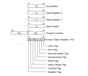
Processor status register (PS)
The processor status register is an 8-bit register consisting of flags which indicate the status of the processor after an arithmetic operation. Branch operations can be performed by testing the Carry (C) flag, Zero (Z) flag, Overflow (V) flag, or the Negative (N) flag. In decimal mode, the Z, V, N flags are not valid.
After reset, the Interrupt disable (I) flag is set to “1”, but all other flags are undefined. Since the Index X mode (T) and Decimal mode (D) flags directly affect arithmetic operations, they should be initialized in the beginning of a program.
- Carry flag (C)
The C flag contains a carry or borrow generated by the arithmetic logic unit (ALU) immediately after an arithmetic operation. It can also be changed by a shift or rotate instruction.
- Zero flag (Z)
The Z flag is set if the result of an immediate arithmetic operation or a data transfer is “0”, and cleared if the result is anything other than “0”.
- Interrupt disable flag (I)
The I flag disables all interrupts except for the interrupt generated by the BRK instruction. Interrupts are disabled when the I flag is “1”.
When an interrupt occurs, this flag is automatically set to “1” to prevent other interrupts from interfering until the current interrupt is serviced.