Readout Texas Instrument TMS320F2801PZA MCU Software
The TMS320F2801PZA has four low-power modes (idle 1, idle 2, PLL power down, and oscillator power down). The low-power modes reduce the operating power by reducing or stopping the activity of various modules from Readout Texas Instrument TMS320F2801PZA MCU Software (by stopping their clocks). The two PLLPM bits of the clock module control register, CKCR0, select which of the low-power modes the device enters when executing an IDLE instruction.
Reset or an unmasked interrupt from any source causes the device to exit from idle 1 low-power mode. A real-time interrupt from the watchdog timer module causes the device to exit from all low-power modes except oscillator power down only after Crack Microcontroller IC TI 430G2452. This is a wake-up interrupt.
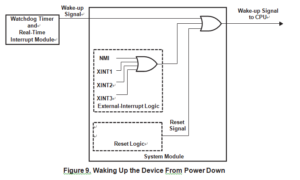
When enabled, reset or any of the four external interrupts (NMI, XINT1, XINT2, or XINT3) causes the device to exit from any of the low-power modes (idle 1, idle 2, PLL power down, and oscillator power down). The external interrupts are all wake-up interrupts in order to Decipher Texas Instruments MCU MSP430G2402. The maskable external interrupts (XINT1, XINT2, and XINT3) must be enabled individually and globally to bring the device out of a low-power mode properly.
It is, therefore, important to ensure that the desired low-power-mode exit path is enabled before entering a low-power mode when MCU reading execution has been completed. below Figure shows the wake-up sequence from a power down. Table 9 summarizes the low-power modes.


