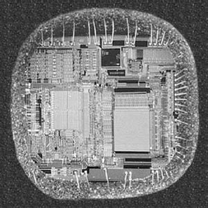
Read Microcontroller ST62T52 Dump
Read Microcontroller ST62T52 Dump first step is to understand the execution principle of interrupt inside Microcontroller:
All interrupts cause the processor to exit from WAIT mode. Only the external and some specific interrupts from the on-chip peripherals cause the processor to exit from STOP mode (refer to the “Exit from STOP“ column in the Interrupt Mapping Table).
This interrupt is triggered when a falling edge oc- curs on the NMI pin regardless of the state of the GEN bit in the IOR register. An interrupt request on NMI vector #0 is latched by a flip flop which is automatically reset by the core at the beginning of the NMI service routine.

Read Microcontroller ST62T52 Dump
Different peripheral interrupt flags in the peripheral control registers are able to cause an interrupt when they are active if both:
– The GEN bit of the IOR register is set
– The corresponding enable bit is set in the periph- eral control register.
Peripheral interrupts are linked to vectors #3 and #4. Interrupt requests are flagged by a bit in their corresponding control register. This means that a request cannot be lost, because the flag bit must be cleared by user software after Copy MCU ST62T60 Flash Heximal.
A Reset can interrupt the NMI and peripheral interrupt routines
The Non Maskable Interrupt request has the highest priority and can interrupt any peripheral interrupt routine at any time but cannot interrupt another NMI interrupt.
No peripheral interrupt can interrupt another. If more than one interrupt request is pending, these are processed by the processor core according to their priority level: vector #1 has the highest priority while vector #4 the lowest. The priority of each interrupt source is fixed by hardware.

