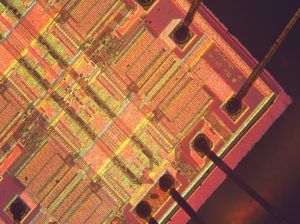
Read IC PIC18F2410 Heximal
Read IC PIC18F2410 and extract the heximal inside the memory, copy the program and data to blank MCU PIC18F2410 which will provide the same functions;

Read IC PIC18F2410 and extract the heximal inside the memory, copy the program and data to blank MCU PIC18F2410 which will provide the same functions;
Power Managed Modes:
Run: CPU on, peripherals on
Idle: CPU off, peripherals on
Sleep: CPU off, peripherals off
Idle mode currents down to 3.0 µA typical
Sleep mode currents down to 20 nA typical
Timer1 Oscillator: 1.8 µA, 32 kHz, 2V
Watchdog Timer: 2.1 µA
Two-Speed Oscillator Start-up
Peripheral Highlights:
· High-current sink/source 25 mA/25 mA
· Up to 2 Capture/Compare/PWM (CCP) modules, one with Auto-Shutdown (28-pin devices)
· Enhanced Capture/Compare/PWM (ECCP) module (40/44-pin devices only):
– One, two or four PWM outputs
– Selectable polarity
– Programmable dead time
– Auto-Shutdown and Auto-Restart
· Master Synchronous Serial Port (MSSP) module supporting 3-wire SPI™ (all 4 modes) and I2C™
Master and Slave Modes
· Enhanced Addressable USART module:
– Supports RS-485, RS-232 and LIN 1.2
– RS-232 operation using internal oscillator block (no external crystal required)
– Auto-Wake-up on Start bit
– Auto-Baud Detect
· 10-bit, up to 13-channel Analog-to-Digital Converter module (A/D):
– Auto-acquisition capability
– Conversion available during Sleep
· Dual analog comparators with input multiplexing
· Programmable 16-level High/Low-Voltage Detection (HLVD) module:
– Supports interrupt on High/Low-Voltage Detection
Flexible Oscillator Structure:
· Four Crystal modes, up to 40 MHz
· 4x Phase Lock Loop (PLL) – available for crystal and internal oscillators
· Two External RC modes, up to 4 MHz
· Two External Clock modes, up to 40 MHz
· Internal oscillator block:
– 8 user selectable frequencies, from 31 kHz to 8 MHz
– Provides a complete range of clock speeds from 31 kHz to 32 MHz when used with PLL
– User tunable to compensate for frequency drift
· Secondary oscillator using Timer1 @ 32 kHz
· Fail-Safe Clock Monitor:
– Allows for safe shutdown if peripheral clock stops
Special Microcontroller Features:
· C compiler optimized architecture:
– Optional extended instruction set designed to optimize re-entrant code
· 100,000 erase/write cycle Flash program memory typical
· Three programmable external interrupts
· Four input-change interrupts
· Priority levels for interrupts
· 8 x 8 Single-Cycle Hardware Multiplier
· Extended Watchdog Timer (WDT):
– Programmable period from 4 ms to 131s
· Single-supply 5V In-Circuit Serial Programming™ (ICSP™) via two pins
· In-Circuit Debug (ICD) via two pins
· Wide operating voltage range: 2.0V to 5.5V
· Programmable Brown-out Reset (BOR) with software enable option
Tags: تكسر ic software,تكسر mcu hex,تكسر الدوائر المتكاملة bin,تكسر رقاقة firmware,تكسر ميكروكنترولر program,فتح ic code,فتح mcu eeprom,فتح الدوائر المتكاملة dump,فتح رقاقة archive,فتح ميكروكنترولر flash

