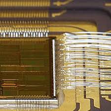
Read Chip PIC16F877 Program
Read Chip PIC16F877 Program from locked flash memory and eeprom memory, and copy the extracted firmware to new MCU PIC16F877 which can provide the same functions for MCU pic16f877 recovery;

PORTC is an 8-bit wide, bi-directional port. The corresponding data direction register is TRISC. Setting a TRISC bit (= 1) will make the corresponding PORTC pin an input (i.e., put the corresponding output driver in a Hi-Impedance mode). Clearing a TRISC bit (= 0) will make the corresponding PORTC pin an output (i.e., put the contents of the output latch on the selected pin) when Read Chip.
PORTC is multiplexed with several peripheral functions When the I2C module is enabled, the PORTC<4:3> pins can be configured with normal I2C levels, or with SMBus levels by using the CKE bit (SSPSTAT<6>) before Read Chip.
When enabling peripheral functions, care should be taken in defining TRIS bits for each PORTC pin. Some peripherals override the TRIS bit to make a pin an output, while other peripherals override the TRIS bit to make a pin an input if Read Chip.
Since the TRIS bit override is in effect while the peripheral is enabled, read-modify-write instructions (BSF, BCF, XORWF) with TRISC as destination, should be avoided. The user should refer to the corresponding peripheral section for the correct TRIS bit settings when Read Chip.
PORTE and TRISE are not implemented on the PORTE has three pins (RE0/RD/AN5, RE1/WR/AN6, and RE2/CS/AN7) which are individually configureable as inputs or outputs. These pins have Schmitt Trigger input buffers after Read Chip.
The PORTE pins become the I/O control inputs for the microprocessor port when bit PSPMODE (TRISE<4>) is set. In this mode, the user must make certain that the TRISE<2:0> bits are set, and that the pins are configured as digital inputs. Also ensure that ADCON1 is configured for digital I/O. In this mode, the input buffers are TTL before Read Chip.
Register 3-1 shows the TRISE register, which also controls the parallel slave port operation. PORTE pins are multiplexed with analog inputs. When selected for analog input, these pins will read as ’0’s. TRISE controls the direction of the RE pins, even when they are being used as analog inputs. The user must make sure to keep the pins configured as inputs when using them as analog inputs when Read Chip.
The Parallel Slave Port (PSP) is not implemented on the PIC16F873 or PIC16F876. PORTD operates as an 8-bit wide Parallel Slave Port or microprocessor port, when control bit PSPMODE (TRISE<4>) is set. In Slave mode, it is asynchronously readable and writable by the external world through RD control input pin RE0/RD and WR control input pin RE1/WR if unlock microcontroller pic16f882 hex.
The PSP can directly interface to an 8-bit microprocessor data bus. The external microprocessor can read or write the PORTD latch as an 8-bit latch. Setting bit PSPMODE enables port pin RE0/RD to be the RD input, RE1/WR to be the WR input and RE2/CS to be the CS (chip select) input. For this functionality, the corresponding data direction bits of the TRISE register (TRISE<2:0>) must be configured as inputs (set).
The A/D port configuration bits PCFG3:PCFG0 (ADCON1<3:0>) must be set to configure pins RE2:RE0 as digital I/O. There are actually two 8-bit latches: one for data output, and one for data input. The user writes 8-bit data to the PORTD data latch and reads data from the port pin latch (note that they have the same address).
In this mode, the TRISD register is ignored, since the external device is controlling the direction of data flow. A write to the PSP occurs when both the CS and WR lines are first detected low. When either the CS or WR lines become high (level triggered), the Input Buffer Full (IBF) status flag bit (TRISE<7>) is set on the Q4 clock cycle, following the next Q2 cycle, to signal the write is complete.
The interrupt flag bit PSPIF (PIR1<7>) is also set on the same Q4 clock cycle. IBF can only be cleared by reading the PORTD input latch. The Input Buffer Overflow (IBOV) status flag bit (TRISE<5>) is set if a second write to the PSP is attempted when the previous byte has not been read out of the buffer.
Tags: read chip flash archive,read chip flash code,read chip flash content,read chip flash data,read chip flash eeprom,read chip flash file,read chip flash firmware,read chip flash information,read chip flash memory,read chip flash program

