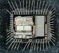
Pull Freescale Microcontroller MC9S12XS128MAL Program
Pull Freescale Microcontroller MC9S12XS128MAL Program from both its eeprom and flash, then transfer it to other blank Microcontroller which will provide the same functions:
Features of the S12XS Family are listed here. Please see Table D-1 for memory options and Table D-2 for
the peripheral features that are available on the different family members.
· 16-bit CPU12X
— Upward compatible with S12 instruction set with the exception of five Fuzzy instructions
(MEM, WAV, WAVR, REV, REVW) which have been removed
— Access to large data segments independent of PPAGE
INT (interrupt module)
— Seven levels of nested interrupts
— Flexible assignment of interrupt sources to each interrupt level.
— External non-maskable high priority interrupt (XIRQ)
— The following inputs can act as Wake-up Interrupts
– IRQ and non-maskable XIRQ
– CAN receive pins
– Depending on the package option up to 20 pins on ports J, H and P configurable as rising or falling edge sensitive MMC (module mapping control) DBG (debug module)
— Monitoring of CPU bus with tag-type or force-type breakpoint requests
— 64 x 64-bit circular trace buffer captures change-of-flow or memory access information BDM (background debug mode) OSC_LCP (oscillator)
— Low power loop control Pierce oscillator utilizing a 4MHz to 16MHz crystal
— Good noise immunity
— Full-swing Pierce option utilizing a 2MHz to 40MHz crystal
— Transconductance sized for optimum start-up margin for typical crystals IPLL (Internally filtered, frequency modulated phase-locked-loop clock generation) by Pull Freescale Microcontroller MC9S12XS128MAL Program
— No external components required
— Configurable option to spread spectrum for reduced EMC radiation (frequency modulation) CRG (clock and reset generation)
— COP watchdog
— Clock monitor
— Fast wake up from STOP in self clock mode
Memory Options
— 64, 128 and 256 Kbyte Flash
– 64 data bits plus 8 syndrome ECC (Error Correction Code) bits allow single bit failure correction and double fault detection
– Erase sector size 1024 bytes
– Automated program and erase algorithm
– Protection scheme to prevent accidental program or erase
– Security option to prevent unauthorized access
– Sense-amp margin level setting for reads
— 4 and 8 Kbyte Data Flash space
– 16 data bits plus 6 syndrome ECC (Error Correction Code) bits allow single bit failure correction and double fault detection
– Erase sector size 256 bytes
– Automated program and erase algorithm
— 4, 8 and 12 Kbyte RAM 16-channel, 12-bit Analog-to-Digital converter
— 8/10/12 Bit resolution
— 3µs, 10-bit single conversion time
— Left or right justified result data
— External and internal conversion trigger capability
— Internal oscillator for conversion in Stop modes
— Wake from low power modes on analog comparison > or <= match
— Continuous conversion mode
— Multiplexer for 16 analog input channels
— Multiple channel scans
— Pins can also be used as digital I/O
MSCAN (1 M bit per second, CAN 2.0 A, B software compatible module)

Pull Freescale Microcontroller MC9S12XS128MAL Program
— 1 Mbit per second, CAN 2.0 A, B software compatible module
– Standard and extended data frames
– 0 – 8 bytes data length
– Programmable bit rate up to 1 Mbps
— Five receive buffers with FIFO storage scheme
— Three transmit buffers with internal prioritization
— Flexible identifier acceptance filter programmable as:
– 2 x 32-bit
– 4 x 16-bit
– 8 x 8-bit
— Wake-up with integrated low pass filter option
— Loop back for self test
— Listen-only mode to monitor CAN bus
— Bus-off recovery by software intervention or automatically
— 16-bit time stamp of transmitted/received messages
TIM (standard timer module)
— 8 x 16-bit channels for input capture or output compare
— 16-bit free-running counter with 8-bit precision prescaler
— 1 x 16-bit pulse accumulator
PIT (periodic interrupt timer)
— Up to four timers with independent time-out periods
— Time-out periods selectable between 1 and 224 bus clock cycles

