NXP Microcontroller P89LPC913 Heximal File Cracking
NXP Microcontroller P89LPC913 Heximal File Cracking start from compromise the timer, when timer 1 is in Mode 3 it is stopped (holds its count). The effect is the same as setting TR1 = 0.
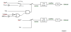
Timer 0 in Mode 3 establishes TL0 and TH0 as two separate 8-bit counters. The logic for Mode 3 and Timer 0 is shown in below Figure. TL0 uses the Timer 0 control bits: T0C/T, T0GATE, TR0, INT0, and TF0. TH0 is locked into a timer function (counting machine cycles) and takes over the use of TR1 and TF1 from Timer 1.
Thus, TH0 now controls the ‘Timer 1’ interrupt.
Mode 3 is provided for applications that require an extra 8-bit timer. With Timer 0 in Mode 3, the P89LPC913 can look like it has an additional Timer.
Note: When Timer 0 is in Mode 3, Timer 1 can be turned on and off by switching it into and out of its own Mode 3. It can still be used by the serial port as a baud rate generator, or in any application not requiring an interrupt to stop the operation of Philip MCU P89C51 Eprom Memory cracking.
Timer 2 is a 16-bit Timer/Counter which can operate as either an event timer or an event counter, as selected by C/T2 in the special function register T2CON. Timer 2 has four operating modes: Capture, Auto-reload (up or down counting), Clock-out, and Baud Rate Generator which are selected


