NXP Chip P89LPC933 Memory Program Cloning
NXP Chip P89LPC933 Memory Program Cloning can start from programmable watchdog timer, it can give the system a malfunctional unit.
The device offers a programmable Watchdog Timer (WDT) for fail safe protection against software deadlock and automatic MCU recovery.
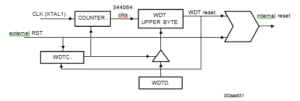
To protect the system against software deadlock, the user software must refresh the WDT within a user-defined time period. If the software fails to do this periodical refresh, an internal hardware reset will be initiated if enabled (WDRE = 1). The software can be designed such that the WDT times out if the program does not work properly.
The WDT in the device uses the system clock (XTAL1) as its time base. So strictly speaking, it is a Watchdog counter rather than a Watchdog timer only after Microcontroller ST62T40 Flash Program Cloning has been completed. The WDT register will increment every 344,064 crystal clocks. The upper 8-bits of the time base register (WDTD) are used as the reload register of the WDT.
The WDTS flag bit is set by WDT overflow and is not changed by WDT reset. User software can clear WDTS by writing ‘1′ to it.
Below Figure provides a block diagram of the WDT. Two SFRs (WDTC and WDTD) control Watchdog timer operation. During idle mode, WDT operation is temporarily suspended, and resumes upon an interrupt exit from idle.
The time-out period of the WDT is calculated as follows: Period = (255 – WDTD) ´ 344064 ´ 1/fCLK (XTAL1)
where WDTD is the value loaded into the WDTD register and fosc is the oscillator frequency.


