Microcontroller ST62T40 Flash Program Cloning
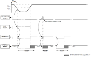
Microntroller ST62T40 Flash Program Cloning can be executed through resetting, hereby we would like to introduce the principal of resetting:
The MCU can be reset in three ways:
A low pulse input on the RESET pin
Internal Watchdog reset
Internal Low Voltage Detector (LVD) reset
The basic RESET sequence consists of 3 main phases:
Internal (watchdog or LVD) or external Reset event
A delay of 2048 or 32768 clock (fINT) cycles (selected through the option bytes) RESET vector fetch, The reset delay allows the oscillator to stabilise and ensures that MCU recovery has taken place from the Reset state into Chip STMicroelectronics ST72C215G2 copying.
The RESET vector fetch phase duration is 2 clock cycles.
When a reset occurs:
– The stack is cleared
– The PC is loaded with the address of the Reset vector. It is located in program ROM starting at address 0FFEh.
A jump to the beginning of the user program must be coded at this address.
– The interrupt flag is automatically set, so that the CPU is in Non Maskable Interrupt mode. This prevents the initialization routine from being interrupted to Clone MCU ST7FMC1K2B6 Program. The initialization routine should therefore be terminated by a RETI instruction, in order to go back to normal mode.
The RESET pin may be connected to a device on the application board in order to reset the MCU if required. The RESET pin may be pulled low in RUN, WAIT or STOP mode. This input can be used to reset the internal state of the MCU and ensure it starts-up correctly. The pin, which is con- nected to an internal pull-up, is active low and features a Schmitt trigger input.
A delay (2048 clock cycles) added to the external signal ensures that even short pulses on the RESET pin are accepted as valid, provided VDD has completed its rising phase and that the oscillator is running correctly (normal RUN or WAIT modes). The MCU is kept in the Reset state as long as the RESET pin is held low.


