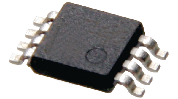
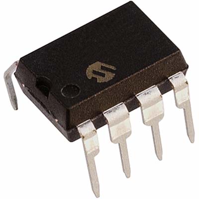
Microchip Secured PIC12F1501T MCU Flash Content Cloning
Microchip Secured PIC12F1501T MCU Flash Content Cloning is going to break off the fuse bit protection over PIC12F1501T locked microcontroller, heximal data of PIC12F1501T can be readout directly from its flash memory;

The overall structure of the code protection on the PIC12F Flash devices differs significantly from other PIC devices. The user program memory is divided into three blocks. One of these is a boot block of 512 bytes. The remainder of the memory is divided into two blocks on binary boundaries.
Each of the three blocks has three protection bits associated with them. They are:
- Code-Protect bit (CPn)
- Write-Protect bit (WRTn)
- External Block Table Read bit (EBTRn)
Figure 19-5 shows the program memory organization for 4 and 8-Kbyte devices and the specific code protec- tion bit associated with each block. The actual locations of the bits are summarized in Table 19-3.
The program memory may be read to, or written from, any location using the table read and table write instructions. The device ID may be read with table reads. The Configuration registers may be read and written with the table read and table write instructions.

In normal execution mode, the CPn bits have no direct effect. CPn bits inhibit external reads and writes. A block of user memory may be protected from table writes if the WRTn Configuration bit is ‘0’ to crack PIC12F1572 secured microprocessor fuse bit. The EBTRn bits control table reads. For a block of user memory with the EBTRn bit set to ‘0’, a table read instruction that executes from within that block is allowed to read.
A table read instruction that executes from a location outside of that block is not allowed to read and will result in reading ‘0’s. Figures 19-6 through 19-8 illustrate table write and table read protection

