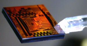
Freescale Chip P87C550 Flash Code Extraction
Freescale Chip P87C550 Flash Code Extraction refers to the internal reset generated by power on, low voltage, and oscillator fail detect circuits are self timed to guarantee proper initialization of the 8XC575. Reset will be held approximately 24 oscillator periods after normal conditions are detected by all enabled detect circuits. Internal resets do not drive RST but will cause missing pulses on ALE.
Interrupt Enable (IE) Register EA
IE.7 enable all interrupts EC
IE.6 enable PCA interrupt
ET2 IE.5 enable Timer 2 interrupt ES
IE.4 enable Serial I/O interrupt ET1
IE.3 enable Timer 1 interrupt EX1
IE.2 enable External interrupt 1 ET0
IE.1 enable Timer 0 interrupt EX0
IE.0 enable External interrupt 0
XTAL1 and XTAL2 are the input and output, respectively, of an inverting amplifier. The pins can be configured for use as an on-chip oscillator, as shown in the Logic Symbol, page 4.
To drive the device from an external clock source, XTAL1 should be driven while XTAL2 is left unconnected. There are no requirements on the duty cycle of the external clock signal, because the input to the internal clock circuitry is through a divide-by-two flip-flop. However, minimum and maximum high and low times specified in the data sheet must be observed.
In idle mode, the CPU puts itself to sleep while all of the on-chip peripherals stay active. The instruction to invoke the idle mode is the last instruction executed in the normal operating mode before the idle mode is activated when extract IC code.
The CPU contents, the on-chip RAM, and all of the special function registers remain intact during this mode. The idle mode can be terminated either by any enabled interrupt (at which time the process is picked up at the interrupt service routine and continued), or by a hardware reset which starts the processor in the same manner as a power-on reset.


