Extract Microcontroller PIC16F747 Code
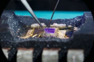
Extract Microcontroller PIC16F747 Code from its embedded flash and eeprom memory, disable the security fuse bit by laser cutting, normally the Microprocessor PIC16F747 reverse engineering process will help to locate the position of MCU and remove the tamper resistance system;

Extract Microcontroller PIC16F747 Code from its embedded flash and eeprom memory, disable the security fuse bit by laser cutting, normally the Microprocessor PIC16F747 reverse engineering process will help to locate the position of MCU and remove the tamper resistance system
Special Microcontroller Features:
· Fail-Safe Clock Monitor for protecting critical applications against crystal failure when Extract Microcontroller code;
· Two-Speed Start-up mode for immediate code execution
· Power-on Reset (POR), Power-up Timer (PWRT) and Oscillator Start-up Timer (OST)
· Programmable Code Protection
· Processor Read Access to Program Memory
· Power-Saving Sleep mode
· In-Circuit Serial Programming (ICSP) via two pins
· MPLAB® In-Circuit Debug (ICD) via two pins
· MCLR pin function replaceable with input only pin if Microcontroller PIC16F616 cracking
DEVICE OVERVIEW
This document contains device specific information about the following devices:
PIC16F737/767 devices are available only in 28-pin packages, while PIC16F747/777 devices are available in 40-pin and 44-pin packages. All devices in the PIC16F7X7 family share common architecture with the following differences:
· The PIC16F737 and PIC16F767 have one-half of the total on-chip memory of the PIC16F747 and PIC16F777 after Extract Microcontroller code.
· The 28-pin devices have 3 I/O ports, while the 40/44-pin devices have 5.
· The 28-pin devices have 16 interrupts, while the 40/44-pin devices have 17.
· The 28-pin devices have 11 A/D input channels, while the 40/44-pin devices have 14.
· The Parallel Slave Port is implemented only on the 40/44-pin devices.
· Low-Power modes: RC_RUN allows the core and peripherals to be clocked from the INTRC, while SEC_RUN allows the core and peripherals to be clocked from the low-power Timer1. Refer to
Section 4.7 “Power-Managed Modes” for further details for the purpose of Microcontroller PIC12F609 hex unlocking.
· Internal RC oscillator with eight selectable frequencies, including 31.25 kHz, 125 kHz, 250 kHz, 500 kHz, 1 MHz, 2 MHz, 4 MHz and 8 MHz. The INTRC can be configured as a primary or secondary clock source. Refer to Section 4.5 “Internal Oscillator Block” for further details.
Tags: extract microcontroller software archive,extract microcontroller software code,extract microcontroller software content,extract microcontroller software data,extract microcontroller software eeprom,extract microcontroller software file,extract microcontroller software firmware,extract microcontroller software information,extract microcontroller software memory,extract microcontroller software program


