-
Product Categories
Live Support Chat


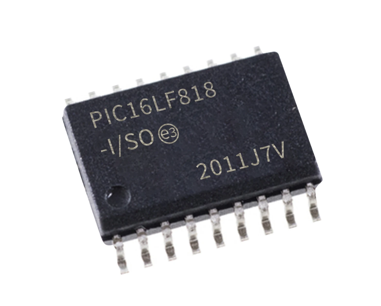
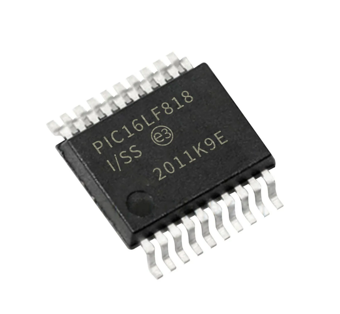
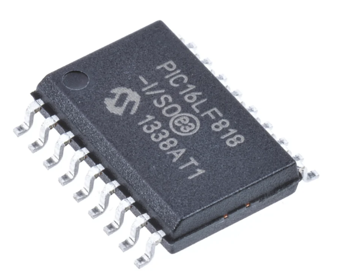
Duplicate Microprocessor PIC16LF818 Memory Code
Duplicate Microprocessor PIC16LF818 Memory Code needs to crack secured microcontroller PIC16LF818 protection system and extract microchip MCU PIC16LF818 encrypted flash program memory and eeprom data memory in the format of binary firmware or heximal file to copy original source firmware;
This document contains device specific information for the operation of the PIC16LF818 devices which would be useful for Duplicate Microprocessor PIC16LF818 Memory Code. Additional information may be found in the “PIC® Mid-Range MCU Family Reference Manual” (DS33023) which may be downloaded from the Microchip web site. The Reference Manual should be considered a complementary document to this data sheet and is highly recommended reading for a better understanding of the device architecture and operation of the peripheral modules when Copy Chip STMicroelectronics ST72C215G2.

The PIC16F818/819 belongs to the Mid-Range family of the PIC® devices. The devices differ from each other in the amount of Flash program memory from Crack ARM MCU STM32F103
, data memory and data EEPROM (see Table 1-1). A block diagram of the devices is shown in Figure 1-1. These devices contain features that are new to the PIC16 product line:
• Internal RC oscillator with eight selectable frequencies, including 31.25 kHz, 125 kHz, 250 kHz, 500 kHz, 1 MHz, 2 MHz, 4 MHz and 8 MHz. The INTRC can be configured as the system clock via the configuration bits to Break IC flash. Refer to Section 4.5 “Internal Oscillator Block” and Section 12.1 “Configuration Bits” for further details.
The Timer1 module current consumption has been greatly reduced from 20 mA (previous PIC16 devices) to 1.8 mA typical (32 kHz at 2V), which is ideal for real-time clock applications to Duplicate Microprocessor PIC16LF818 Memory Code. Refer to Section 6.0 “Timer0 Module” for further details.
The amount of oscillator selections has increased after Microntroller ST62T40 Flash Program Cloning. The RC and INTRC modes can be selected with an I/O pin configured as an I/O or a clock output (FOSC/4). An external clock can be configured with an I/O pin. Refer to Section 4.0 “Oscillator Configurations” for further details.
There are 16 I/O pins that are user configurable on a pin-to-pin basis to Read MCU PIC16F874 Eeprom. Some pins are multiplexed with other device functions. These functions include:
External Interrupt
Change on PORTB Interrupt
Timer0 Clock Input
Low-Power Timer1 Clock/Oscillator
Capture/Compare/PWM
10-bit, 5-channel Analog-to-Digital Converter
SPI/I2C
MCLR (RA5) can be configured as an Input Table 1-2 details the pinout of the devices with descriptions and details for each pin.