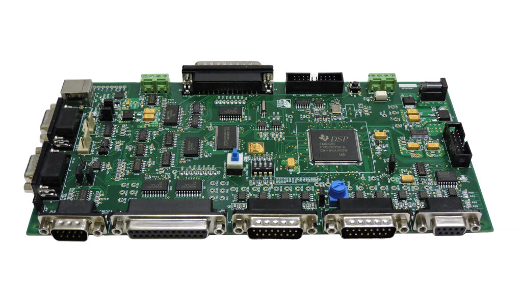
DSP IC MCU TMS320LF2402PGS Flash Program Replication
DSP IC MCU TMS320LF2402PGS Flash Program Replication is a process to breaking off TMS320LF2402PGS locked microcontroller security fuse bit and then unlock binary file out from protected DSP Microprocessor TMS320LF2402PGS flash memory;

- Software-generated interrupts for the ’LF240x devices include:
- The INTR instruction. This instruction allows initialization of any ’LF240x interrupt with software. Its operand indicates the interrupt vector location to which the CPU branches. This instruction globally disables maskable interrupts (sets the INTM bit to 1).
- The NMI instruction. This instruction forces a branch to interrupt vector location 24h. This instruction globally disables maskable interrupts. ’240x devices do not have the NMI hardware signal, only software activation is provided.
- The TRAP instruction. This instruction forces the CPU to branch to interrupt vector location 22h. The TRAP instruction does not disable maskable interrupts (INTM is not set to 1); therefore, when the CPU branches to the interrupt service routine, that routine can be interrupted by the maskable hardware interrupts.
- An emulator trap. This interrupt can be generated with either an INTR instruction or a TRAP instruction.
Six core interrupts (INT1–INT6) are expanded using a peripheral interrupt expansion (PIE) module identical to the ’F24x devices to decrypt mcu tms320lf2407apge flash memory. The PIE manages all the peripheral interrupts from the ’240x peripherals and are grouped to share the six-core level interrupts. Figure 7 shows the PIE block diagram for hardware-generated interrupts.

The PIE diagram (Figure 7) and the interrupt table (Table 3) explain the grouping and interrupt vector maps. ’LF240x devices have interrupts identical to the ’F24x devices and should be completely code-compatible. ’240x devices also have peripheral interrupts identical to the ’F24x – plus additional interrupts for new peripherals such as event manager B and then reverse dsp mcu tms320lf2401av flash program. Though the new interrupts share the ’24x interrupt grouping, they all have a unique vector to differentiate among the interrupts. See Table 3 for details.

