Decrypt P87LPC762 Locked Memory Program
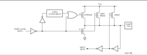
After Decrypt P87LPC762 Locked Memory Program, the correct configuration bits will be able to make the program transferring to new memory and make it works as original version. A second pull-up, called the “weak” pull-up, is turned on when the port latch for the pin contains a logic 1 and the pin itself is also at a logic 1 level. This pull-up provides the primary source current for a quasi-bidirectional pin that is outputting a 1.
If a pin that has a logic 1 on it is pulled low by an external device, the weak pull-up turns off, and only the very weak pull-up remains on. In order to pull the pin low under these conditions, the external device has to sink enough current to overpower the weak pull-up and take the voltage on the port pin below its input threshold when recover program from MCU.
The third pull-up is referred to as the “strong” pull-up. This pull-up is used to speed up low-to-high transitions on a quasi-bidirectional port pin when the port latch changes from a logic 0 to a logic 1 by Philip Chip LPC87LPC761 Heximal Code cloning. When this occurs, the strong pull-up turns on for a brief time, two CPU clocks, in order to pull the port pin high quickly. Then it turns off again.
The quasi-bidirectional port configuration is shown in below Figure.
Open Drain Output Configuration
The open drain output configuration turns off all pull-ups and only drives the pull-down transistor of the port driver when the port latch contains a logic 0. To be used as a logic output, a port configured in this manner must have an external pull-up, typically a resistor tied to VDD. The pull-down for this mode is the same as for the quasi-bidirectional mode.
Push-Pull Output Configuration
The push-pull output configuration has the same pull-down structure as both the open drain and the quasi-bidirectional output modes, but provides a continuous strong pull-up when the port latch contains a logic 1. The push-pull mode may be used when more source current is needed from a port output.


