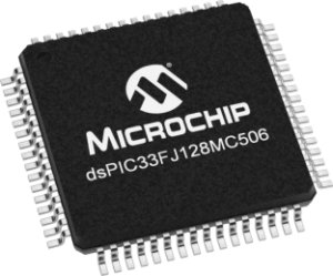
Decode Microcomputer IC Microchip DSPIC33FJ128MC506
Decode Microcomputer IC Microchip DSPIC33FJ128MC506
Decode Microcomputer IC Microchip DSPIC33FJ128MC506
The dsPIC33F devices (Rev. A2) you received were found to conform to the specifications and functionality described in the following documents:
· DS70165 – “dsPIC33F Family Data Sheet”
· DS70157 – “dsPIC30F/33F Programmer’s
Reference Manual”
· DS70046 – “dsPIC30F Family Reference Manual” dsPIC33F Rev. A2 silicon is identified by performing a “Reset and Connect” operation to the device using MPLAB® ICD 2 with MPLAB IDE v7.40 or later. The output window will show a successful connection to the device specified in Configure>Select Device .
The errata described in this section will be addressed in future revisions of silicon.
Silicon Errata Summary
The following list summarizes the errata described in further detail through the remainder of this document:
The exceptions to the specifications in the documents listed above are described in this section. The specific devices for which these exceptions are described are listed below Doze Mode
When Doze mode is enabled, any writes to a peripheral SFR can cause other updates to that register to cease to function for the duration of the current CPU clock cycle.
12-bit Analog-to-Digital Converter (ADC) Module
For this revision of silicon, the 12-bit ADC module
INL, DNL and signal acquisition time parameters are not within the published data sheet specifications. 10-bit ADC Module
For this revision of silicon, the 10-bit ADC module
DNL, conversion speed and signal acquisition time parameters are not within the published data sheet specifications.
DMA Module: Interaction with EXCH Instruction
The EXCH instruction does not execute correctly when one of the operands contains a value equal to the address of the DMAC SFRs.
DISI Instruction
The DISI instruction will not disable interrupts if a
DISI instruction is executed in the same instruction cycle that the DISI counter decrements to zero.
Motor Control PWM
Output Compare Module
The output compare module will produce a glitch on the output when an I/O pin is initially set high and the module is configured to drive the pin low at a specified time.
Output Compare Module in PWM Mode
SPI Module in Frame Master Mode
1. Module: Oscillator: Doze Mode
Enabling Doze mode slows down the CPU but allows peripherals to run at full speed. When the CPU clock is slowed down by enabling Doze mode (CLKDIV<11> = 1), any writes to a peripheral SFR can cause other updates to that register to cease to function for the duration of the current CPU clock cycle. This is only an issue if the CPU attempts to write to the same register as a peripheral while in Doze mode. For instance, if the ADC module is active and Doze The SPI module will fail to generate frame synchronization pulses in Frame Master mode.
10. SPI Module in Slave Select Mode
The SPI module Slave Select functionality will not work correctly.
11. SPI Module
The SMP bit does not have any effect when the SPI module is configured for a 1:1 prescale factor in Master mode.
12. ECAN™ Module
ECAN transmissions may be incorrect if multiple transmit buffers are simultaneously queued for transmission.
13. ECAN Module
Under specific conditions, the first five bits of a transmitted identifier may not match the value in the transmit buffer ID register.
14. ECAN Module Loopback Mode
The ECAN module (ECAN1 or ECAN2) does not function correctly in Loopback mode.
15. I2C™ Module
The bus collision status bit does not get set when a bus collision occurs during a Restart or Stop event.
16. INT0, ADC and Sleep/Idle Mode ADC event triggers from the INT0 pin will not wake-up the device from Sleep or Idle mode if the SMPI bits are non-zero.
17. Doze Mode and Traps
18. JTAG Programming
JTAG programming does not work.
The following sections will describe the errata and work around to these errata, where they may apply.


