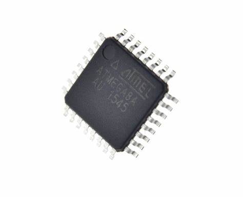
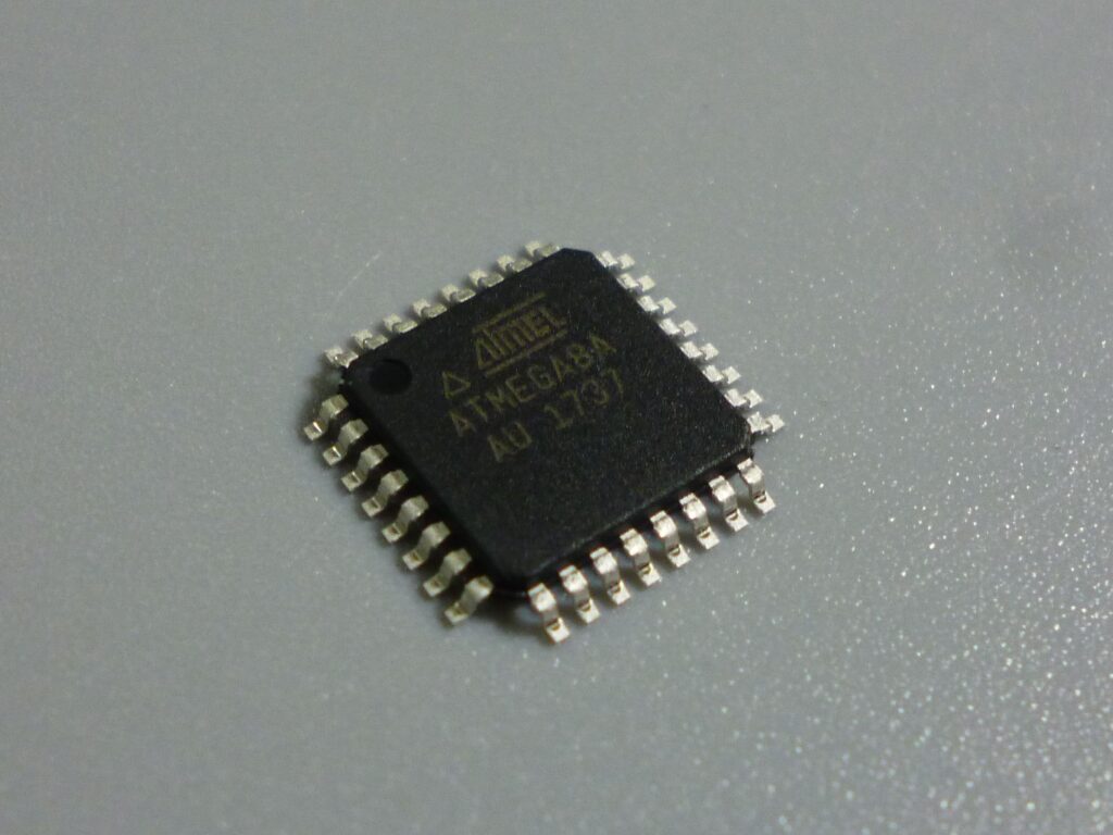
Decode ATmega8A Microprocessor Heximal Data
Decode ATmega8A Microprocessor Heximal Data from its secured flash memory, the fuse bit of microchip atmega8a will be attacked, extract binary firmware from MCU ATmega8A;

This section describes the general access timing concepts for instruction execution. The Microchip AVR® CPU is driven by the CPU clock clkCPU, directly generated from the selected clock source for the chip. No internal clock division is used.
Below shows the parallel instruction fetches and instruction executions enabled by the Harvard architecture and the fast-access Register File concept when break protected atmega8l mcu locked memory. This is the basic pipelining concept to obtain up to 1 MIPS per MHz with the corresponding unique results for functions per cost, functions per clocks, and functions per power-unit.

The Microchip AVR® provides several different interrupt sources. These interrupts and the separate Reset Vector each have a separate Program Vector in the Program memory space. All interrupts are assigned individual enable bits to unlock atmega8 microchip avr microcontroller flash program which must be written logic one together with the Global Interrupt Enable bit in the Status Register in order to enable the interrupt.

Depending on the Program Counter value, interrupts may be automatically disabled when Boot Lock Bits BLB02 or BLB12 are programmed. This feature improves software security. See the section “Memory Programming” on page 214 for details..
Tags: descifrar archivo binario de memoria de microordenador protegido,descifrar microcontrolador protegido eeprom datos heximal,descifrar programa de firmware incrustado MCU IC cifrado,descifrar software de memoria flash de microprocesador bloqueado

