Crack Philip MCU P87C749 Flash Program
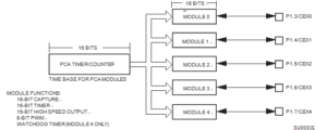
The Programmable Counter Array is a special Timer which is very critical in the process of Crack Philip MCU P87C749 Flash Program, has five 16-bit capture/compare modules associated with it. Each of the modules can be programmed to operate in one of four modes: rising and/or falling edge capture, software timer, high-speed output, or pulse width modulator. Each module has a pin associated with it in port 1 by Readout MCU program. Module 0 is connected to P1.3(CEX0), module 1 to P1.4(CEX1), etc.. The basic PCA configuration is shown in below Figure.
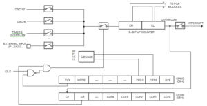
The PCA timer is a common time base for all five modules and can be programmed to run at: 1/12 the oscillator frequency, 1/4 the oscillator frequency, the Timer 0 overflow, or the input on the ECI pin (P1.2).
The timer count source is determined from the CPS1 and CPS0 bits in the CMOD SFR as follows (see below Figure):
CPS1 CPS0 PCA Timer Count Source
1/12 oscillator frequency
1 1/4 oscillator frequency
0 Timer 0 overflow
External Input at ECI pin
In the CMOD SFR are three additional bits associated with the PCA. They are CIDL which allows the PCA to stop during idle mode in the process of Clone Philip Microprocessor P89C638 Flash Program, WDTE which enables or disables the watchdog function on module 4, and ECF which when set causes an interrupt and the PCA overflow flag CF (in the CCON SFR) to be set when the PCA timer overflows.


