Crack MCU PIC16F724 Binary
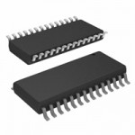
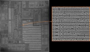
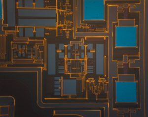
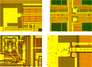
Crack MCU PIC16F724 flash memory and read secured Binary of microcontroller pic16f724 which will be used to make MCU firmware recovering;
The PIC16F72X/PIC16LF72X device family features an interruptible core, allowing certain events to preempt normal program flow. An Interrupt Service Routine (ISR) is used to determine the source of the interrupt and act accordingly. Some interrupts can be configured to wake the MCU from Sleep mode.
Interrupts are disabled upon any device Reset. They are enabled by setting the following bits:
· GIE bit of the INTCON register
· Interrupt Enable bit(s) for the specific interrupt event(s)
· PEIE bit of the INTCON register (if the Interrupt if Crack MCU
Enable bit of the interrupt event is contained in the PIE1 and PIE2 registers)
The INTCON, PIR1 and PIR2 registers record individual interrupts via Interrupt Flag bits. Interrupt Flag bits will be set, regardless of the status of the GIE, PEIE and individual Interrupt Enable bits before Crack MCU.
The following events happen when an interrupt event occurs while the GIE bit is set:
interrupt that occurs while executing the ISR will be recorded through its Interrupt Flag, but will not cause the processor to redirect to the interrupt vector. The RETFIE instruction exits the ISR by popping the previous address from the stack and setting the GIE bit after Crack MCU.
For additional information on a specific interrupt’s operation, refer to its peripheral chapter.
Note 1: Individual Interrupt Flag bits are set, regardless of the state of any other enable bits.
2: All interrupts will be ignored while the GIE bit is cleared. Any interrupt occurring while the GIE bit is clear will be serviced when the GIE bit is set again if Crack MCU.
· Current prefetched instruction is flushed
· GIE bit is cleared
· Current Program Counter (PC) is pushed onto the stack
· PC is loaded with the interrupt vector 0004h
The ISR determines the source of the interrupt by polling the Interrupt Flag bits. The Interrupt Flag bits must be cleared before exiting the ISR to avoid repeated interrupts. Because the GIE bit is cleared, any interrupt that occurs while executing the ISR will be recorded through its Interrupt Flag, but will not cause the processor to redirect to the interrupt vector when Crack MCU pic16f721 flash.
The RETFIE instruction exits the ISR by popping the previous address from the stack and setting the GIE bit. For additional information on a specific interrupt’s operation, refer to its peripheral chapter. Some interrupts can be used to wake from Sleep.
To wake from Sleep, the peripheral must be able tooperate without the system clock. The interrupt source must have the appropriate Interrupt Enable bit(s) set prior to entering Sleep. On waking from Sleep, if the GIE bit is also set, the processor will branch to the interrupt vector. Otherwise, the processor will continue executing instructions after the SLEEP instruction.
The instruction directly after the SLEEP instruction will always be executed before branching to the ISR. Refer to the Section 19.0 “Power-Down Mode (Sleep)” for more details. The external interrupt, INT pin, causes an asynchronous, edge-triggered interrupt.
The INTEDG bit of the OPTION register determines on which edge the interrupt will occur. When the INTEDG bit is set, the rising edge will cause the interrupt. When the INTEDG bit is clear, the falling edge will cause the interrupt. The INTF bit of the INTCON register will be set when a valid edge appears on the INT pin. If the GIE and INTE bits are also set, the processor will redirect program execution to the interrupt vector. This interrupt is disabled by clearing the INTE bit of the INTCON register.
When an interrupt occurs, only the return PC value is saved to the stack. If the ISR modifies or uses an instruction that modifies key registers, their values must be saved at the beginning of the ISR and restored when the ISR completes. This prevents instructionsfollowing the ISR from using invalid data.
Examples of key registers include the W, STATUS, FSR and PCLATH registers. Since most instructions modify the W register, it must be saved immediately upon entering the ISR. The SWAPF instruction is used when saving and restoring the W and STATUS registers because it will not affect any bits in the STATUS register.
It is useful to place W_TEMP in shared memory because the ISR cannot predict which bank will be selected when the interrupt occurs. The processor will branch to the interrupt vector by loading the PC with 0004h. The PCLATH register will remain unchanged.
This requires the ISR to ensure that the PCLATH register is set properly before using an instruction that causes PCLATH to be loaded into the PC. See Section 2.3 “PCL and PCLATH” for details on PC operation.
Tags: crack mcu flash archive,crack mcu flash code,crack mcu flash content,crack mcu flash data,crack mcu flash eeprom,crack mcu flash file,crack mcu flash firmware,crack mcu flash information,crack mcu flash memory,crack mcu flash program


