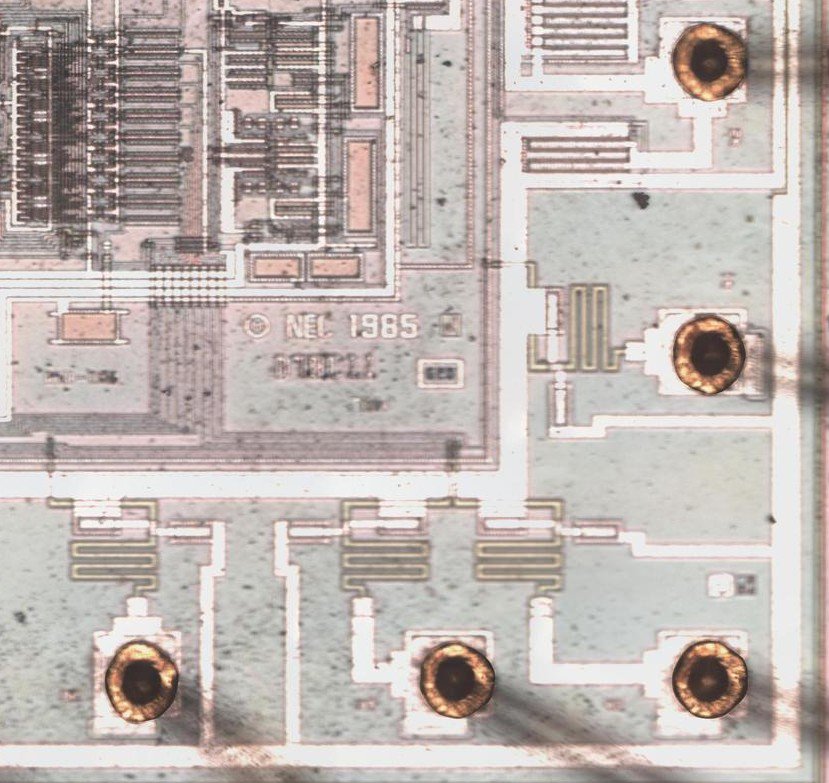
Crack MCU PIC12F675 Binary
Crack MCU PIC12F675 locked memory and recover binary of microcontroller flash and eeprom memory, the file include data and program can be replicated to blank Microprocessor for perfect cloning;
Crack MCU PIC12F675 locked memory and recover binary of microcontroller flash and eeprom memory, the file include data and program can be replicated to blank Microprocessor for perfect cloning
This document contains device specific information for the PIC12F629/675. Additional information may be found in the PIC® Mid-Range Reference Manual (DS33023), which may be obtained from your local Microchip Sales Representative or downloaded from the Microchip web site. The Reference Manual should be considered a complementary document to this Data Sheet, and is highly recommended reading for a better understanding of the device architecture and operation of the peripheral modules.
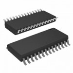
The PIC12F629 and PIC12F675 devices are covered by this Data Sheet. They are identical, except the PIC12F675 has a 10-bit A/D converter. They come in 8-pin PDIP, SOIC, MLF-S and DFN packages. Figure 1-1 shows a block diagram of the PIC12F675 devices. Table 1-1 shows the pinout description after crack MCU PIC18F2439 memory.
The PIC12F629/675 devices have a 13-bit program counter capable of addressing an 8K x 14 program memory space. Only the first 1K x 14 (0000h-03FFh) for the PIC12F629/675 devices is physically implemented. Accessing a location above these boundaries will cause a wrap-around within the first 1K x 14 space.
The Reset vector is at 0000h and the interrupt vector is at 0004h if crack nxp MCU LPC2361.
The data memory (see Figure 2-2) is partitioned into two banks, which contain the General Purpose locations of each bank. Register locations 20h-5Fh are General Purpose Registers, implemented as static RAM and are mapped across both banks. All other RAM is unimplemented and returns ‘0’ when read. RP0 (STATUS<5>) is the bank select bit.
Registers and the Special Function Registers. The Special Function Registers are located in the first 32 locations of each bank. Register locations 20h-5Fh are General Purpose Registers, implemented as static RAM and are mapped across both banks. All other RAM is unimplemented and returns ‘0’ when read. RP0 (STATUS<5>) is the bank select bit.
Tags: crack mcu flash archive,crack mcu flash code,crack mcu flash content,crack mcu flash data,crack mcu flash eeprom,crack mcu flash file,crack mcu flash firmware,crack mcu flash information,crack mcu flash memory,crack mcu flash program


