Crack IC PIC12F629 Program
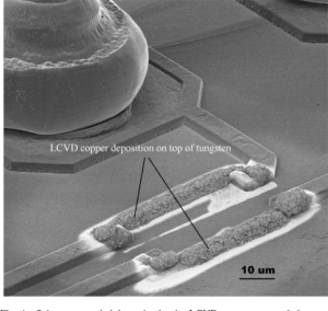
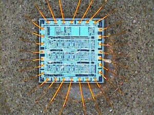
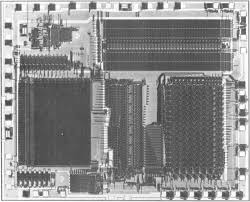
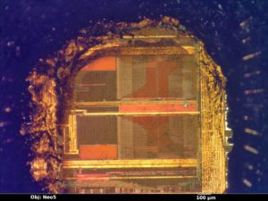
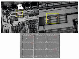
Crack IC PIC12F629 needs to find out MCU’s security fuse bit location through the Microcontroller circuitry pattern schematic, then disable the bit by laser cutting and recover microcomputer’s Program from flash memory;
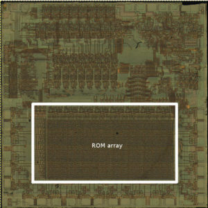
Crack IC PIC12F629 needs to find out MCU’s security fuse bit location through the Microcontroller circuitry pattern schematic, then disable the bit by laser cutting and recover microcomputer’s Program from flash memory
High-Performance RISC CPU:
· Only 35 Instructions to Learn
– All single-cycle instructions except branches
· Operating Speed:
– DC – 20 MHz oscillator/clock input
– DC – 200 ns instruction cycle
· Interrupt Capability
· 8-Level Deep Hardware Stack
· Direct, Indirect, and Relative Addressing modes
Special Microcontroller Features:
· Internal and External Oscillator Options
– Precision Internal 4 MHz oscillator factory calibrated to ±1%
– External Oscillator support for crystals and resonators
– 5 ms wake-up from Sleep, 3.0V, typical
· Power-Saving Sleep mode
· Wide Operating Voltage Range – 2.0V to 5.5V
· Industrial and Extended Temperature Range
· Low-Power Power-on Reset (POR)
· Power-up Timer (PWRT) and Oscillator Start-up Timer (OST)
· Brown-out Detect (BOD)
· Watchdog Timer (WDT) with Independent Oscillator for Reliable Operation
· Multiplexed MCLR/Input Pin
· Interrupt-on-Pin Change
· Individual Programmable Weak Pull-ups
· Programmable Code Protection
· High Endurance Flash/EEPROM Cell
– 100,000 write Flash endurance
– 1,000,000 write EEPROM endurance
– Flash/Data EEPROM Retention: > 40 years
Low-Power Features:
· Standby Current:
– 1 nA @ 2.0V, typical
· Operating Current:
– 8.5 mA @ 32 kHz, 2.0V, typical
– 100 mA @ 1 MHz, 2.0V, typical
· Watchdog Timer Current
– 300 nA @ 2.0V, typical
· Timer1 Oscillator Current:
– 4 mA @ 32 kHz, 2.0V, typical
Peripheral Features:
· 6 I/O Pins with Individual Direction Control
· High Current Sink/Source for Direct LED Drive
· Analog Comparator module with:
– One analog comparator
– Programmable on-chip comparator voltage reference (CVREF) module
– Programmable input multiplexing from device inputs
– Comparator output is externally accessible
· Analog-to-Digital Converter module (PIC12F675):
– 10-bit resolution
– Programmable 4-channel input
– Voltage reference input
· Timer0: 8-Bit Timer/Counter with 8-Bit Programmable Prescaler
· Enhanced Timer1:
– 16-bit timer/counter with prescaler
– External Gate Input mode
– Option to use OSC1 and OSC2 in LP mode as Timer1 oscillator, if INTOSC mode selected
· In-Circuit Serial ProgrammingTM (ICSPTM) via two pins
Tags: crack ic heximal archive,crack ic heximal code,crack ic heximal content,crack ic heximal data,crack ic heximal eeprom,crack ic heximal file,crack ic heximal firmware,crack ic heximal information,crack ic heximal memory,crack ic heximal program


