Crack IC ATMEGA48PA Heximal
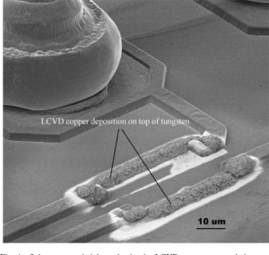
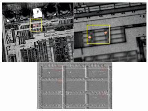
Crack IC ATMEGA48PA and readout the MCU firmware from flash and eeprom memory, the file format will be Heximal or binary, ATmega48PA Microcontroller security fuse bit can be disable through focus ion beam technique and cut it off to disable the protective mechanism;
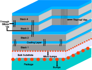
Crack IC ATMEGA48PA and readout the firmware from flash and eeprom memory, the file format will be Heximal or binary, ATmega48PA Microcontroller security fuse bit can be disable through focus ion beam technique and cut it off to disable the protective mechanism
Overrides T0CS bit for TRIS control of GP2, When the comparator is turned on, these control bits assert themselves. When the comparator is off, these bits have no effect on the device operation and the other control registers have precedence.
The on-board comparator inputs, (GP0/CIN+, GP1/ CIN-), as well as the comparator output (GP2/COUT), are steerable. The CMCON0, OPTION and TRIS registers are used to steer these pins.
If the Comparator mode is changed, the comparator output level may not be valid for the specified mode change delay shown in Table 12-1 after pull mcu stmicroelectronics program.
A single comparator is shown in Figure 8-2 along with the relationship between the analog input levels and the digital output. When the analog input at VIN+ is less than the analog input VIN-, the output of the comparator is a digital low level.
When the analog input at VIN+ is greater than the analog input VIN-, the output of the comparator is a digital high level. The shaded areas of the output of the comparator in Figure 8-2 represent the uncertainty due to input offsets and response time.
The comparator output is read through CMCON0 register. This bit is read-only. The comparator output may also be used internally, The comparator wake-up flag is set whenever all of the following conditions are met when pull freescale microcontroller program:
· CWU = 0 (CMCON0<0>)
· CMCON0 has been read to latch the last known state of the CMPOUT bit (MOVF CMCON0, W)
· Device is in Sleep
· The output of the comparator has changed state
The wake-up flag may be cleared in software or by another device Reset
An internal reference signal may be used depending on the comparator operating mode. The analog signal that is present at VIN- is compared to the signal at VIN+ and the digital output of the comparator is adjusted accordingly (Figure 8-2). Please see Table 12-1 for internal reference specifications.
Tags: crack ic heximal archive,crack ic heximal code,crack ic heximal content,crack ic heximal data,crack ic heximal eeprom,crack ic heximal file,crack ic heximal firmware,crack ic heximal information,crack ic heximal memory,crack ic heximal program


