Crack Chip PIC18F43K20 Program
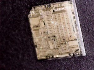
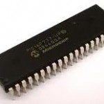
Crack Chip PIC18F43K20 tamper resistance system and dump program out from flash memory, data from eeprom memory, the firmware can be rewrite into to new PIC18F43K20 MCU by a universal programmer after installed on the socket adapter, recover code from microprocessor PIC18F43K20;

Crack Chip PIC18F43K20 tamper resistance system and dump program out from flash memory, data from eeprom memory, the firmware can be rewrite into to new PIC18F43K20 MCU by a universal programmer after installed on the socket adapter, recover code from microprocessor PIC18F43K20
The Internal Oscillator Frequency Select bits (IRCF<2:0>) select the frequency output of the internal oscillator block. The choices are the LFINTOSC source (31 kHz), the HFINTOSC source (16 MHz) or one of the frequencies derived from the HFINTOSC postscaler (31.25 kHz to 8 MHz).
If the internal oscillator block is supplying the main clock, changing the states of these bits will have an immediate change on the internal oscillator’s output. On device Resets, the output frequency of the internal oscillator is set to the default frequency of 1 MHz if microcontroller PIC12F617 bin extraction.
When a nominal output frequency of 31 kHz is selected (IRCF<2:0> = 000), users may choose which internal oscillator acts as the source. This is done with the INTSRC bit of the OSCTUNE register. Setting this bit selects the HFINTOSC as a 31.25 kHz clock source by enabling the divide-by-512 output of the HFINTOSC postscaler.
Clearing INTSRC selects LFINTOSC (nominally 31 kHz) as the clock source. This option allows users to select the tunable and more precise HFINTOSC as a clock source, while maintaining power savings with a very low clock speed. Regardless of the setting of INTSRC, LFINTOSC always remains the clock source for features such as the Watchdog Timer and the Fail-Safe Clock Monitor.
PIC18F2XK20/4XK20 devices contain circuitry to prevent clock “glitches” when switching between clock sources. A short pause in the device clock occurs during the clock switch. The length of this pause is the sum of two cycles of the old clock source and three to four cycles of the new clock source if MCU PIC16HV540 Bin unlocking.
This formula assumes that the new clock source is stable. Clock Source modes can be classified as external or internal.
· External Clock modes rely on external circuitry for the clock source. Examples are: Clock modules (EC mode), quartz crystal resonators or ceramic resonators (LP, XT and HS modes) and Resistor-Capacitor (RC mode) circuits.
· Internal clock sources are contained internally within the Oscillator block. The Oscillator block has two internal oscillators: the 16 MHz High-Frequency Internal Oscillator (HFINTOSC) and the 31 kHz Low-Frequency Internal Oscillator (LFINTOSC) before PIC16HV616 Chip EEPROM Unlocking.
The system clock can be selected between external or internal clock sources via the System Clock Select (SCS<1:0>) bits of the OSCCON register. When the Oscillator module is configured for LP, XT or HS modes, the Oscillator Start-up Timer (OST) counts 1024 oscillations from OSC1.
This occurs following a Power-on Reset (POR) and when the Power-up Timer (PWRT) has expired (if configured), or a wake-up from Sleep. During this time, the program counter does not increment and program execution is suspended. The OST ensures that the oscillator circuit, using a quartz crystal resonator or ceramic resonator, has started and is providing a stable system clock to the Oscillator module.
When switching between clock sources, a delay is required to allow the new clock to stabilize. These oscillator delays are shown in Table 2-1. In order to minimize latency between external oscillator start-up and code execution, the Two-Speed Clock Start-up mode can be selected.
Tags: crack chip heximal archive,crack chip heximal code,crack chip heximal content,crack chip heximal data,crack chip heximal eeprom,crack chip heximal file,crack chip heximal firmware,crack chip heximal information,crack chip heximal memory,crack chip heximal program


