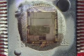
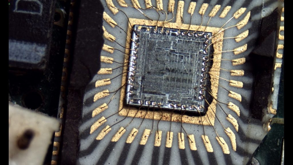
Crack Chip AT89C51IC2 Software
Crack Chip AT89C51IC2 program memory and extract data memory Software in the format of heximal, break microcontroller AT89C51IC2 for MCU cloning;
The X2 bit in the CKCON0 register (see Table 19) allow to switch from 12 clock periods per instruction to 6 clock periods and vice versa. At reset, the speed is setting according to X2 bit of Hardware Security Byte (HSB). By default, Standard mode is actived.
Setting the X2 bit activates the X2 feature (X2 mode). The T0X2, T1X2, T2X2, UartX2, PcaX2, WdX2 and I2CX2 bits in the CKCON0 register (See Table 19.) and SPIX2 bit in the CKCON1 register (see Table 20) allow to switch from standard peripheral speed (12 clock periods per peripheral clock cycle) to fast peripheral speed (6 clock periods per peripheral clock cycle) if Crack IC dsPIC30F5011 heximal.
These bits are active only in X2 mode. More information about the X2 mode can be found in the application note “How to take advantage of the X2 features in TS80C51 microcontroller”.
The AT89C51IC2 provides additional Bytes of random access memory (RAM) space for increased data parameter handling and high level language usage. AT89C51IC2 devices have expanded RAM in external data space; maximum size and location are described in Table 22.
The AT89C51IC2 has internal data memory that is mapped into four separate segments. The four segments are:
1. The Lower 128 bytes of RAM (addresses 00h to 7Fh) are directly and indirectly addressable.
2. The Upper 128 bytes of RAM (addresses 80h to FFh) are indirectly addressable only.
3. The Special Function Registers, SFRs, (addresses 80h to FFh) are directly addressable only.
4. The expanded RAM bytes are indirectly accessed by MOVX instructions, and with the EXTRAM bit cleared in the AUXR register (see Table 22) The lower 128 bytes can be accessed by either direct or indirect addressing. The Upper 128 bytes can be accessed by indirect addressing.
The Upper 128 bytes occupy the same address space as the SFR. That means they have the same address, but are physically separate from SFR space.
Tags: crack chip binary archive,crack chip binary code,crack chip binary content,crack chip binary data,crack chip binary eeprom,crack chip binary file,crack chip binary firmware,crack chip binary information,crack chip binary memory,crack chip binary program


