Copy NXP Microcontroller P89LPC916 Secured Program
Power supply glitch method can be applied onto the process of Copy NXP Microcontroller P89LPC916 Secured Program,
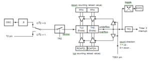
Where Supply Frequency is either fosc (C/T2 = 0) or frequency of signal on T2 pin (C/T2 = 1).
If EXEN2 = 1, a 16-bit reload can be triggered either by an overflow or by a 1-to-0 transition at input T2EX. This transition also sets the EXF2 bit. The Timer 2 interrupt, if enabled, can be generated when either TF2 or EXF2 is ‘1’.
Crack Microcontroller’s hardware will need three consecutive machine cycles in order to recognize falling edge on T2EX and set EXF2 = 1: in the first machine cycle pin T2EX has to be sampled as ‘1’; in the second machine cycle it has to be sampled as ‘0’, and in the third machine cycle EXF2 will be set to ‘1’.
In below Figure, DCEN = 1 and Timer 2 is enabled to count up or down. This mode allows pin T2EX to control the direction of count. When a logic ‘1’ is applied at pin T2EX Timer 2 will count up.
Timer 2 will overflow at 0FFFFH and set the TF2 flag, which can then generate an interrupt, if the interrupt is enabled. This timer overflow also causes the 16-bit value in RCAP2L and RCAP2H to be reloaded into the timer registers TL2 and TH2. When a logic 0 is applied at pin T2EX this causes Timer 2 to count down to facilitate the process of NXP P89LPC908 Chip Secured Code Cracking. The timer will underflow when TL2 and TH2 become equal to the value stored in RCAP2L and RCAP2H.

Copy NXP Microcontroller P89LPC916 Secured Program
Timer 2 underflow sets the TF2 flag and causes 0FFFFH to be reloaded into the timer registers TL2 and TH2. The external flag EXF2 toggles when Timer 2 underflows or overflows. This EXF2 bit can be used as a 17th bit of resolution if needed.


