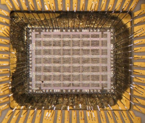
Clone MCU ST7FMC1K2B6 Program
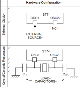
Due to the PCB re-manufacturing reason which has applied ST7FMC1K2B6 as its MCU, engineer need to Clone MCU ST7FMC1K2B6 Program from both its eeprom and flash area out from it, sequence trick can be played on the databus to disable the data transmission process, in order to take advantage of the CPU processing interval it is necessary to have some idea about their oscillator, The main clock of the ST7 can be generated by a crystal or ceramic resonator oscillator or an external source. The associated hardware configurations are shown in below Table. Refer to the electrical characteristics section for more details.
External Clock Source
In this external clock mode, a clock signal (square, sinus or triangle) with ~50% duty cycle has to drive the OSC1 pin while the OSC2 pin is not connected.

Clone MCU ST7FMC1K2B6 Program
Crystal/Ceramic Oscillators
This family of oscillators has the advantage of producing a very accurate rate on the main clock of the ST7. In this mode, the resonator and the load capacitors have to be placed as close as possible to the oscillator pins in order to minimize output distortion and start-up stabilization time.
This oscillator is not stopped during the RESET phase to avoid losing time in its start-up phase. See Electrical Characteristics for more details. Note: When crystal oscillator is used as a clock source, a risk of failure may exist if no series resistors are implemented.


