-
Product Categories
Live Support Chat


Clone MCU MC68HC711K4 Memory Program
Clone MCU MC68HC711K4 Memory Program and data, and then move the program and data to other blank MC68HC711K4 will create an exactly same MCU with the same functions:
The actual acquisition and lock times can be calculated using the equations below. These equations yield nominal values under the following conditions:
- Correct selection of filter capacitor, CF
- Room temperature operation
- Negligible external leakage on CGMXFC
- Negligible noise
The K factor in the equations is derived from internal PLL parameters. KACQ is the K factor when the PLL is configured in acquisition mode, and KTRK is the K factor when the PLL is configured in tracking mode.
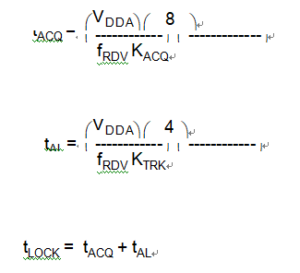
Note the inverse proportionality between the lock time and the reference frequency.
In automatic bandwidth control mode the acquisition and lock times are quantized into units based on the reference frequency. See 9.4.2.3 Manual and Automatic PLL Bandwidth Modes. A certain number of clock cycles, nACQ, is required to ascertain whether the PLL is within the tracking mode entry tolerance TRK, before exiting acquisition mode. Also, a certain number of clock cycles, nTRK, is required to ascertain whether the PLL is within the lock mode entry tolerance DLOCK.
Therefore, the acquisition time tACQ, is an integer multiple of nACQ/fRDV, and the acquisition to lock time tAL, is an integer multiple of nTRK/fRDV. Also, since the average frequency over the entire measurement period must be within the specified tolerance, the total time usually is longer than tLOCK as calculated above.
Clone MCU MC68HC711K4 Memory Program
In manual mode, it is usually necessary to wait considerably longer than tLOCK before selecting the PLL clock, Influences On Reaction Time may slow the lock time considerably.