-
Product Categories
Live Support Chat


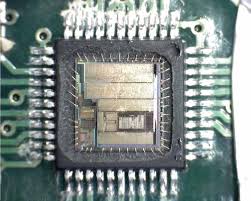
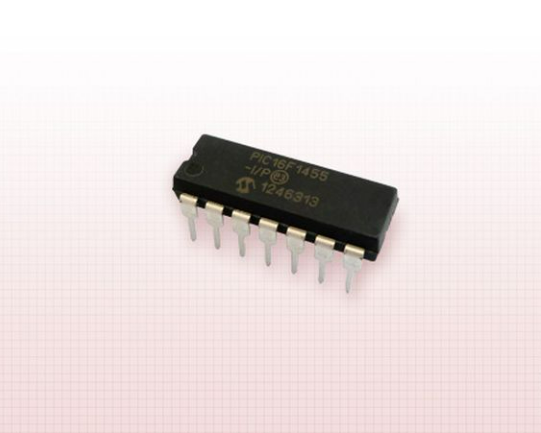
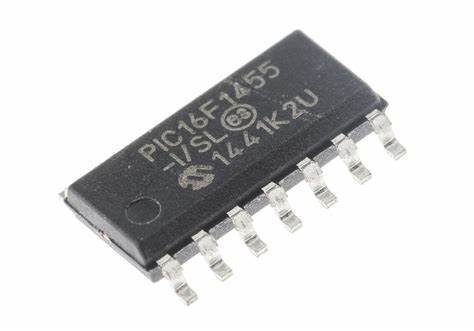
Microchip Controller PIC16F1455 Memory Unlocking
Microchip Controller PIC16F1455 Memory Unlocking will refer to break microprocessor PIC16F1455 protective system, then dump the program memory content out, and copy the firmware into blank PIC16F1455 MCU;
Microchip Controller PIC16F1455 can be programmed using either the high- voltage In-Circuit Serial Programming™ (ICSP™) method or the low-voltage ICSP™ method. When using low-voltage ICSP™ programming (LVP = 1), the ICSPDAT/ICSPCLK functions are additionally enabled on the RA0/RA1 port pins. This legacy programming feature provides compatibility support for existing PIC18F1XK50 designs. For new designs, using the ICSPDAT/ICSPCLK functions on the RC0/RC1 port pins is recommended.
HIGH-VOLTAGE ICSP PROGRAMMING
In High-Voltage ICSP™ mode, these devices require two programmable power supplies: one for VDD and one for the MCLR/VPP pin.
LOW-VOLTAGE ICSP PROGRAMMING
In Low-Voltage ICSP™ mode, these devices can be programmed using a single VDD source in the operating range. The MCLR/VPP pin does not have to be brought to a different voltage, but can instead be left at the normal operating voltage especially in the process of PIC12C508 Flash content reading.
Single-Supply ICSP Programming
The LVP bit in Configuration Word 2 enables single- supply (low-voltage) ICSP programming. The LVP bit defaults to a ‘1’ (enabled) from the factory. The LVP bit may only be programmed to ‘0’ by entering the High- Voltage ICSP mode, where the MCLR/VPP pin is raised to VIHH. Once the LVP bit is programmed to a ‘0’, only the High-Voltage ICSP mode is available and only the High-Voltage ICSP mode can be used to program the device same as the progress of MC68HC711PH8 Microcontroller Eprom Software Duplication.

Note 1: The High-Voltage ICSP mode is always available, regardless of the state of the LVP bit, by applying VIHH to the MCLR/ VPP pin.
2: While in Low-Voltage ICSP mode, MCLR is always enabled, regardless of the MCLRE bit, and the port pin can no longer be used as a general purpose input.