-
Product Categories
Live Support Chat


Freescale MC68HC11KS2 Memory Program Cloning
PLL bandwidth control register is critical for Freescale MC68HC11KS2 Memory Program Cloning, and it has multiple functions as below:
The PLL bandwidth control register does the following:
Selects automatic or manual (software-controlled) bandwidth control mode
Indicates when the PLL is locked
In automatic bandwidth control mode, indicates when the PLL is in acquisition or tracking mode can be executed by IC Breaking
In manual operation, forces the PLL into acquisition or tracking mode.
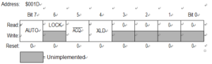
PLL Bandwidth Control Register (PBWC)
AUTO — Automatic Bandwidth Control Bit
This read/write bit selects automatic or manual bandwidth control. When initializing the PLL for manual operation (AUTO = 0), the ACQ bit should be cleared before turning the PLL on. Reset clears the AUTO bit to Unlock Freescale MC68HC11E9 Encrypted Heximal
1 = Automatic bandwidth control 0 = Manual bandwidth control
LOCK — Lock Indicator Bit
When the AUTO bit is set, LOCK is a read-only bit that becomes set when the VCO clock CGMVCLK, is locked (running at the programmed frequency). When the AUTO bit is clear, LOCK reads as 0 and has no meaning. Reset clears the LOCK bit.
1 = VCO frequency correct or locked
0 = VCO frequency incorrect or unlocked
ACQ — Acquisition Mode Bit
When the AUTO bit is set, ACQ is a read-only bit that indicates whether the PLL is in acquisition mode or tracking mode from Freescale MC68HC11KS2 Memory Program Cloning. When the AUTO bit is clear, ACQ is a read/write bit that controls whether the PLL is in acquisition or tracking mode.
In automatic bandwidth control mode (AUTO = 1), the last-written value from manual operation is stored in a temporary location and is recovered when manual operation resumes. Reset clears this bit, enabling acquisition mode through the process of Restore NXP P89LPC922 Microcontroller Flash Heximal.
Freescale MC68HC11KS2 Memory Program Cloning
1 = Tracking mode
0 = Acquisition mode
XLD — Crystal Loss Detect Bit
When the VCO output, CGMVCLK, is driving CGMOUT, this read/write bit indicates whether the crystal reference frequency is active or not. To check the status of the crystal reference, the following procedure should be followed:
1. Write a 1 to XLD.
2. Wait 4 N cycles. (N is the VCO frequency multiplier.)
3. Read XLD.
1 = Crystal reference is not active 0 = Crystal reference is active
The crystal loss detect function works only when the BCS bit is set, selecting CGMVCLK to drive CGMOUT. When BCS is clear, XLD always reads as 0.
Bits [3:0] — Reserved for test
These bits enable test functions not available in user mode. To ensure software portability from development systems to user applications, software should write zeros to Bits [3:0] whenever writing to PBWC.