Unlock Philip P87C654 MCU Locked Eprom
There are some other important features which are also critical to Unlock Philip P87C654 MCU Locked Eprom, which refers to power, low voltage detection, oscillator failure detection and low active reset.
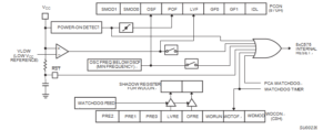
An on-chip Power On Detect Circuit resets the 8XC575 and sets the Power Off Flag (PCON.4) on power up or if VCC drops to zero momentarily. The POF can only be cleared by software. The RST pin is not driven by the power on detect circuit. The POF can be read by software to determine that a power failure has occurred and can also be set by software.
An on-chip Low Voltage Detect circuit sets the Low Voltage Flag (PCON.3) if VCC drops below VLOW (see DC Electrical Characteristics) and resets the 8XC654 if the Low Voltage Reset Enable bit (WDCON.4) is set. If the LVRE is cleared, the reset is disabled but LVF will still be set if VCC is low. The RST pin is not driven by the low voltage detect circuit only when the process has been completed by NXP Microprocessor P87L51FA Source Code cloning. The LVF can be read by software to determine that VCC was low. The LVF can be set or cleared by software after Unlock Philip P87C654 MCU Locked Eprom.
An on-chip Oscillator Fail Detect circuit sets the Oscillator Fail Flag (PCON.5) if the oscillator frequency drops below OSCF for one or more cycles (see AC Electrical Characteristics: OSCF) and resets the 8XC654 if the Oscillator Fail Reset Enable bit (WDCON.3) is set. If OFRE is cleared, the reset is disabled but OSF will still be set if the oscillator fails. The RST pin is not driven by the oscillator fail detect circuit. The OSF can be read by software to determine that an oscillator failure has occurred. The OSF can be set or cleared by software.
One of the most notable features on this part is the low active reset. At this time this is the only 80C51 derivative available that has low active reset to extract IC firmware. This feature makes it easier to interface the 8XC675 into an application to accommodate the power-on and low voltage conditions that can occur.
The low active reset operates exactly the same as high active reset with the exception that the part is put into the reset mode by applying a low level to the reset pin. For power-on reset it is also necessary to invert the power-on reset circuit; connecting the 8.2K resistor from the reset pin to VCC and the 10f capacitor from the reset pin to ground. Below Figure shows all of the reset related circuitry.


