Unlock Microcontroller ST7FMC1K2B3 Embedded Flash Code
Reset the sequence of Microcontroller ST7FMC1K2B3 could be another important route of tampering the protection mechanism, when we try to Unlock Microcontroller ST7FMC1K2B3 Embedded Flash Code, through resetting the sequence timer can effective interrupt the order processing sequence specify by the central processing unit, and also there is a manager which could be very helpful for doing that, today we are going to introduce some of the most features of this RSM:
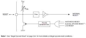
The reset sequence manager includes three RESET sources as shown in below Figure:
External RESET source pulse
Internal LVD RESET (Low Voltage Detection)
Internal WATCHDOG RESET
Note: A reset can also be triggered following the detection of an illegal opcode or prebyte code. Refer to section 11.2.1 on page 244 for further details.

Unlock Microcontroller ST7FMC1K2B3 Embedded Flash Code
These sources act on the RESET pin and it is always kept low during the delay phase.
The RESET service routine vector is fixed at addresses FFFEh-FFFFh in the ST7 memory map.
The basic RESET sequence consists of 3 phases as shown in below Figure:
Active Phase depending on the RESET source
256 or 4096 CPU clock cycle delay (selected by option byte)
RESET vector fetch
Caution: When the ST7 is unprogrammed or fully erased, the Flash is blank and the RESET vector is not programmed. For this reason, it is recom- mended to keep the RESET pin in low state until programming mode is entered, in order to avoid unwanted behavior.
The 256 or 4096 CPU clock cycle delay allows the oscillator to stabilise and ensures that recovery has taken place from the Reset state. The shorter or longer clock cycle delay should be selected by option byte to correspond to the stabilization time of the external oscillator used in the application.
The RESET vector fetch phase duration is 2 clock cycles.


