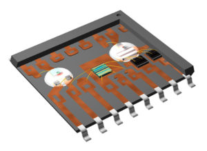
Crack Chip PIC18F2410 Dump
Crack Chip PIC18F2410 Dump can help customer to restore the firmware from its memory and clone the code to other blank PIC18F2410 which can provide the same functions:
When using the DAC in S/H mode, ensure that none of the channels is running at maximum conversion rate, or ensure that the conversion rate of both channels is high enough to not require refresh.
BOD will be enabled after any reset
If any reset source goes active, the BOD will be enabled and keep the device in reset if the VCC voltage is below the programmed BOD level. During Power-On Reset, reset will not be released until VCC is above the programmed BOD level even if the BOD is disabled.
Problem fix/Workaround
Do not set the BOD level higher than VCC even if the BOD is not used.
Both DFLLs and both oscillators has to be enabled for one to work
In order to use the automatic runtime calibration for the 2 MHz or the 32MHz internal oscillators, the DFLL for both oscillators and both oscillators has to be enabled for one to work.
Problem fix/Workaround
Enabled both the DFLLs and both oscillators when using automtics runtime calibartion for one of the internal oscillators.
Operating Frequancy and Voltage Limitation
To ensure correct operation, there is a limit on operating frequnecy and voltage. Figure 36-2 on page 95 shows the safe operating area.
Bandgap voltage input for the ACs cannot be changed when used for both ACs simultaneously
ADC gain stage output range is limited to 2.4V
Sampled BOD in Active mode will cause noise when bandgap is used as reference
Bandgap measurement with the ADC is non-functional when VCC is below 2.7V
BOD will be enabled after any reset
Writing EEPROM or Flash while reading any of them will not work after the ADC has increased INL error for some operating conditions DAC has increased INL or noise for some operating conditions VCC voltage scaler for AC is non-linear Maximum operating frequency below 1.76V is 8 MHz.


