-
Product Categories
Live Support Chat


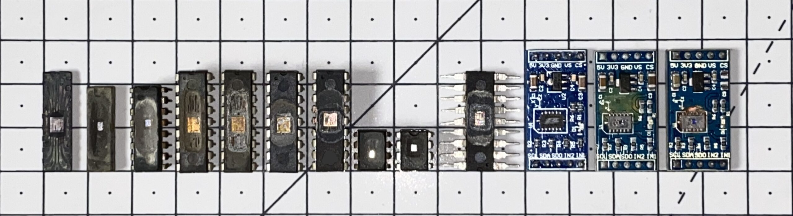
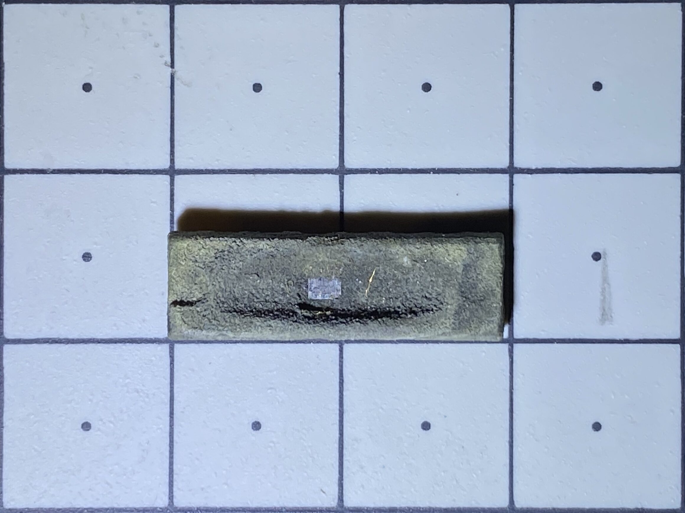
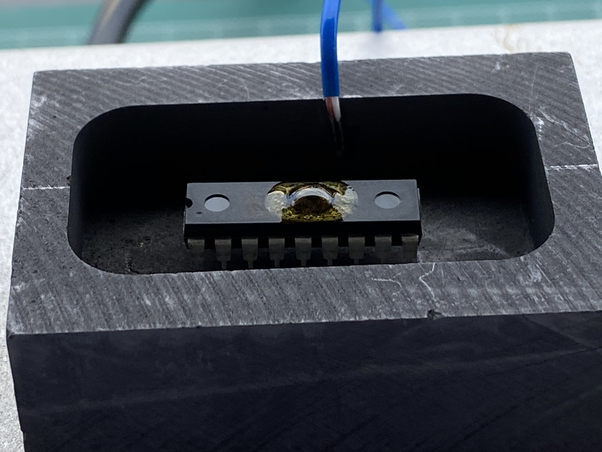
Unlock MCU PIC16F870-I/SP Microchip
The PIC16F870-I/SP from Microchip Technology is a reliable and widely used microcontroller (MCU), favored for its simplicity, efficiency, and broad application in embedded systems, consumer electronics, and automation. Like many modern microcontrollers, it includes integrated security mechanisms to protect internal firmware, binary files, and flash memory from unauthorized access or duplication. However, in certain legitimate scenarios—such as system recovery, legacy support, or failure analysis—there may be a need to unlock microcontroller PIC16F870-I/SP and retrieve critical data.
Why Unlocking May Be Necessary
Organizations often rely on customized programs and firmware developed specifically for the PIC16F870-I/SP chip. Over time, these systems may require maintenance, replication, or migration to newer platforms. Unfortunately, original source files or development backups may be lost or corrupted. In such cases, engineers seek to retrieve, extract, or readout the existing program directly from the MCU to ensure business continuity or maintain device operability.
The goal may be to dump the internal flash, EEPROM, or heximal data, and then replicate or duplicate the program for further use. This process may involve accessing locked memory regions, decoding protected binary content, and ultimately recreating or analyzing the original source code.
Security Features and Challenges
The PIC16F870-I/SP is designed with robust security features, such as code protection bits, which prevent straightforward access to internal firmware. These locked mechanisms are implemented to deter unauthorized cloning, cracking, or hacking attempts and to protect the intellectual property embedded in the chip.
Some of the key challenges in the unlocking process include:
Secured Flash Memory: The program memory is configured to resist external readout, making the retrieval of stored data archives highly complex.
Encrypted Storage: In many cases, even if memory is accessed, the firmware may be stored in an encrypted or encoded format, requiring further steps to decrypt or decode the content.
Debug Interface Restrictions: Standard tools may be disabled due to locked debugging protocols, limiting traditional open or diagnostic access.
Risk of Data Loss: Attempting to break the protection may trigger fail-safe responses in the microcontroller, such as automatic memory erasure.
Advanced Techniques and Ethical Boundaries
While there are advanced methods that can be used to crack, decapsulate, or reverse engineer microcontrollers like the PIC16F870-I/SP, these techniques are typically reserved for security researchers and professionals operating under strict legal frameworks. Physical methods such as chip decapsulation or microprobing are highly specialized, requiring controlled environments and sophisticated equipment.
Any form of attack, whether software- or hardware-based, to clone, unlock, or extract firmware from a protected chip must be approached with legal caution. These procedures should only be carried out with explicit permission from the rightful owner of the hardware and the intellectual property it contains.
Conclusion
Unlocking the PIC16F870-I/SP microcontroller is a technically challenging task due to its secured architecture and data protection mechanisms. Although it is possible to retrieve, replicate, or read out the internal memory under specific conditions, it requires in-depth expertise and, most importantly, must be done within legal and ethical boundaries. For companies dealing with legacy hardware or lost firmware, consulting with certified embedded security professionals is the safest and most responsible way to proceed.
Oscillator Start-up Timer (OST)
· Watchdog Timer (WDT) with its own on-chip RC oscillator for reliable operation
· Programmable code protection
· Power saving SLEEP mode
· Selectable oscillator options
· Low power, high speed CMOS FLASH/EEPROM technology
· Fully static design
· In-Circuit Serial Programmingä (ICSPä) via two pins
· Single 5V In-Circuit Serial Programming capability
· In-Circuit Debugging via two pins
· Processor read/write access to program memory
· Wide operating voltage range: 2.0V to 5.5V
· High Sink/Source Current: 25 mA
· Commercial and Industrial temperature ranges
· Low power consumption:
– < 1.6 mA typical @ 5V, 4 MHz
– 20 mA typical @ 3V, 32 kHz
– < 1 mA typical standby current
Peripheral Features:
· Timer0: 8-bit timer/counter with 8-bit prescaler
· Timer1: 16-bit timer/counter with prescaler, can be incremented during SLEEP via external crystal/clock
· Timer2: 8-bit timer/counter with 8-bit period register, prescaler and postscaler
· One Capture, Compare, PWM module
– Capture is 16-bit, max. resolution is 12.5 ns
– Compare is 16-bit, max. resolution is 200 ns
– PWM max. resolution is 10-bit
· 10-bit multi-channel Analog-to-Digital converter
· Universal Synchronous Asynchronous Receiver
Transmitter (USART/SCI) with 9-bit address detection
· Parallel Slave Port (PSP) 8-bits wide, with external RD, WR and CS controls (40/44-pin only)
· Brown-out detection circuitry for Brown-out Reset (BOR)