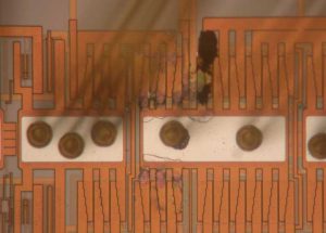
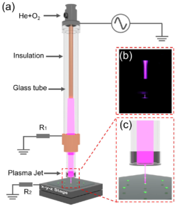
Read IC PIC18F8627 Software
Read IC PIC18F8627 Software from its memory like flash and eeprom, then duplicate the firmware to other blank Microcontroller PIC18F8627 for the same functions;
The 4x Phase Locked Loop (PLL) can be used with the internal oscillator block to produce faster device clock speeds than are normally possible with the internal oscillator sources. When enabled, the PLL produces a clock speed of 16 MHz or 32 MHz.
Unlike HSPLL mode, the PLL is controlled through software. The control bit, PLLEN (OSCTUNE<6>), is used to enable or disable its operation. The PLL is available when the device is configured to use the internal oscillator block as its primary clock source (FOSC<3:0> = 1001 or 1000).
Additionally, the PLL will only function when the selected output frequency is either 4 MHz or 8 MHz (OSCCON<6:4> = 111 or 110). If both of these conditions are not met, the PLL is disabled and the PLLEN bit remains clear (writes are ignored).
The factory calibrates the internal oscillator block output (INTOSC) for 8 MHz. However, this frequency may drift as VDD or temperature changes and can affect the controller operation in a variety of ways. It is possible to adjust the INTOSC frequency by modifying the value in the OSCTUNE register. Depending on the device, this may have no effect on the INTRC clock source frequency.
Tuning the INTOSC source requires knowing when to make the adjustment, in which direction it should be made and in some cases, how large a change is needed. Three compensation techniques are discussed in Section 2.6.5.1 “Compensating with the EUSART”, Section 2.6.5.2 “Compensating with the Timers” and Section 2.6.5.3 “Compensating with the CCP Module in Capture Mode” but other techniques may be used.
An adjustment may be required when the EUSART begins to generate framing errors or receives data with errors while in Asynchronous mode. Framing errors indicate that the device clock frequency is too high. To adjust for this, decrement the value in OSCTUNE to reduce the clock frequency and this drawback will be take advantage for microcontroller content copying. On the other hand, errors in data may suggest that the clock speed is too low.
To compensate, increment OSCTUNE to increase the clock frequency. This technique compares device clock speed to some reference clock. Two timers may be used; one timer is clocked by the peripheral clock, while the other is clocked by a fixed reference source, such as the Timer1 oscillator.
Both timers are cleared, but the timer clocked by the reference generates interrupts. When an interrupt occurs, the internally clocked timer is read and both timers are cleared. If the internally clocked timer value is much greater than expected, then the internal oscillator block is running too fast. To adjust for this, decrement the OSCTUNE register.
A CCP module can use free running Timer1 (or Timer3), clocked by the internal oscillator block and an external event with a known period (i.e., AC power frequency). The time of the first event is captured in the CCPRxH:CCPRxL registers and is recorded for use later. When the second event causes a capture, the time of the first event is subtracted from the time of the second event. Since the period of the external event is known, the time difference between events can be calculated.
If the measured time is much greater than the calculated time, the internal oscillator block is running too fast. To compensate, decrement the OSCTUNE register. If the measured time is much less than the calculated time, the internal oscillator block is running too slow. To compensate, increment the OSCTUNE register.
Tags: read ic locked archive,read ic locked code,read ic locked content,read ic locked data,read ic locked eeprom,read ic locked file,read ic locked firmware,read ic locked information,read ic locked memory,read ic locked program


