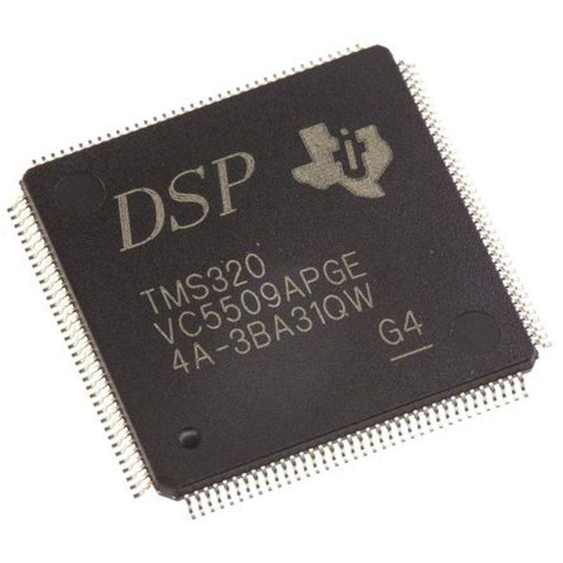
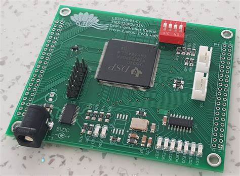
Unlock DSP Microprocessor TMS320F28032PN Flash Embedded Program
Unlock DSP Microprocessor TMS320F28032PN Flash Embedded Program and recover flash memory firmware from dsp microcontroller tms320f28032pn, original flash code of mcu tms320f28032pn can be extracted;

On-chip crystal-oscillator output. A quartz crystal or a ceramic resonator must be connected across X1 and X2. If X2 is not used, it must be left unconnected.
Device Reset (in) and Watchdog Reset (out). These devices have a built-in power-on reset (POR) and brown-out reset (BOR) circuitry. During a power-on or brown-out condition, this pin is driven low by the device.
An external circuit may also drive this pin to assert a device reset. This pin is also driven low by the MCU when a watchdog reset occurs. During watchdog reset, the XRS pin is driven low for the watchdog reset duration of 512 OSCCLK cycles. A resistor with a value from 2.2 kΩ to 10 kΩ should be placed between XRS and VDDIO.
If a capacitor is placed between XRS and VSS for noise filtering, it should be 100 nF or smaller. These values will allow the watchdog to properly drive the XRS pin to VOL within 512 OSCCLK cycles when the watchdog reset is asserted to clone dsp mcu tms320f28023das flash program. Regardless of the source, a device reset causes the device to terminate execution.

The program counter points to the address contained at the location 0x3F FFC0. When reset is deactivated, execution begins at the location designated by the program counter. The output buffer of this pin is an open-drain device with an internal pullup. (↑) If this pin is driven by an external device, it should be done using an open-drain device.
Tags: copie o programa incorporado do flash do microprocessador DSP TMS320F28032PN,Desbloqueie o programa incorporado do flash do microprocessador DSP TMS320F28032PN,recuperar DSP Microprocessador TMS320F28032PN Flash Embedded Program,restaurar DSP Microprocessador TMS320F28032PN Flash Embedded Program

