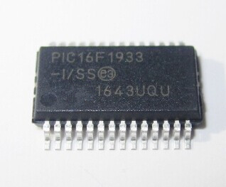
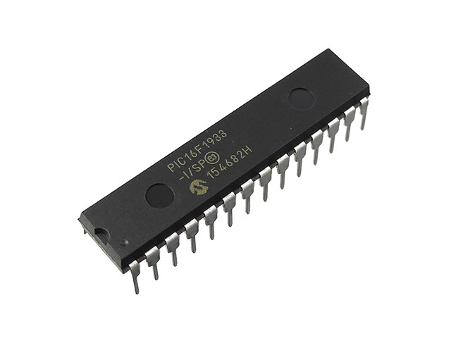
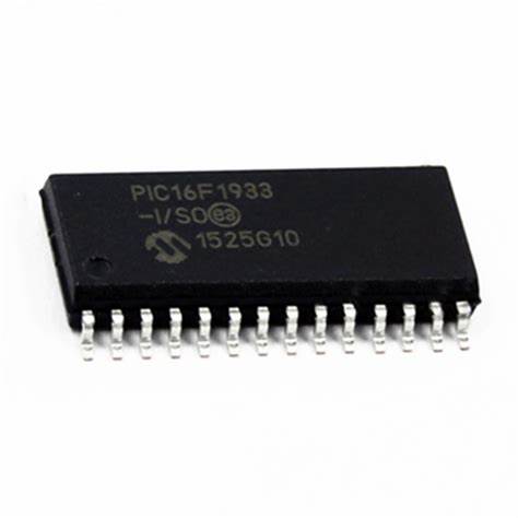
Crack Microchip MCU PIC16F1933T Flash Memory
Crack Microchip MCU PIC16F1933T Flash Memory is processing the microcontroller security fuse bit through MCU breaking technique, and then extract embedded firmware from pic16f1933t microprocessor flash memory in the format of binary or heximal;

The Synchronous Master mode is entered by setting the CSRC bit (TXSTA<7>). In this mode, the data is transmitted in a half-duplex manner (i.e., transmission and reception do not occur at the same time). When transmitting data, the reception is inhibited and vice versa.
Synchronous mode is entered by setting bit, SYNC (TXSTA<4>). In addition, enable bit, SPEN (RCSTA<7>), is set in order to configure the RB1/AN5/ TX/CK/INT1 and RB4/AN6/RX/DT/KBI0 I/O pins to CK (clock) and DT (data) lines, respectively.
The Master mode indicates that the processor trans- mits the master clock on the CK line. Clock polarity is selected with the SCKP bit (BAUDCTL<5>); setting SCKP sets the Idle state on CK as high, while clearing the bit sets the Idle state as low. This option is provided to support Microwire devices with this module.

The EUSART transmitter block diagram is shown. The heart of the transmitter is the Transmit (Serial) Shift Register (TSR). The shift register obtains its data from the Read/Write Transmit Buffer register, TXREG. The TXREG register is loaded with data in software.

The TSR register is not loaded until the last bit has been transmitted from the previous load. As soon as the last bit is transmitted, the TSR is loaded with new data from the TXREG (if available).

