Crack TI Microcontroller TMS320F28032 Memory
When the CPU acknowledges a maskable hardware interrupt in the process of Crack TI Microcontroller TMS320F28032 Memory, it jams the instruction bus with the INTR instruction. This instruction forces the PC to the appropriate address from which the CPU fetches the software vector. This vector leads to an interrupt service routine.
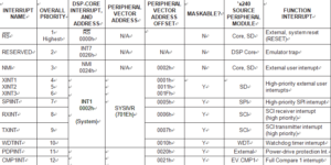
Usually, the interrupt service routine reads the peripheral-vector-address offset from the peripheral-vector- address register to Secured Microcomputer PIC16F84 Flash Unlocking (see below Table) to branch to code that is meant for the specific interrupt source that initiated the interrupt request.
The 28032 includes a phantom-interrupt vector offset (0000h), which is a system interrupt integrity feature that allows a controlled exit from an improper interrupt sequence. If the CPU acknowledges a request from a peripheral when, in fact, no peripheral has requested an interrupt, the phantom-interrupt vector is read from the interrupt-vector register for the purpose of Crack Microchip PIC12F510 Locked Memory.
Above Table summarizes the interrupt sources, overall priority, vector address/offset, source, and function of each interrupt available on the TMS320F28032.
The TMS320F28032 has five external interrupts. These interrupts include:
XINT1. Type A interrupt. The XINT1 control register (at 7070h) provides control and status for this interrupt. XINT1 can be used as a high-priority (Level 1) or low-priority (Level 6) maskable interrupt or as a general-purpose input pin. XINT1 can also be programmed to trigger an interrupt on either the rising or the falling edge.
NMI. Type A interrupt. The NMI control register (at 7072h) provides control and status for this interrupt. NMI is a nonmaskable external interrupt or a general-purpose input pin. NMI can also be programmed to trigger an interrupt on either the rising or the falling edge.
XINT2. Type C interrupt. The XINT2 control register (at 7078h) provides control and status for this interrupt. XINT2 can be used as a high-priority (Level 1) or low-priority (Level 6) maskable interrupt or a general-purpose I/O pin. XINT2 can also be programmed to trigger an interrupt on either the rising or the falling edge when Read Microcontroller ST62T52 Dump.
XINT3. Type C interrupt. The XINT3 control register (at 707Ah) provides control and status for this interrupt. XINT3 can be used as a high-priority (Level 1) or low-priority (Level 6) maskable interrupt or as a general-purpose I/O pin to achieve the goal of Unlock Freescale MC908GT16 Eeprom Memory. XINT3 can also be programmed to trigger an interrupt on either the rising or the falling edge.
PDPINT. This interrupt is provided for safe operation of the power converter and motor drive. This maskable interrupt can put the timers and PWM output pins in the high-impedance state and inform the CPU in case of motor drive abnormalities such as overvoltage by Copy Microcontroller, overcurrent, and excessive temperature rise. PDPINT is a Level 2 interrupt.


