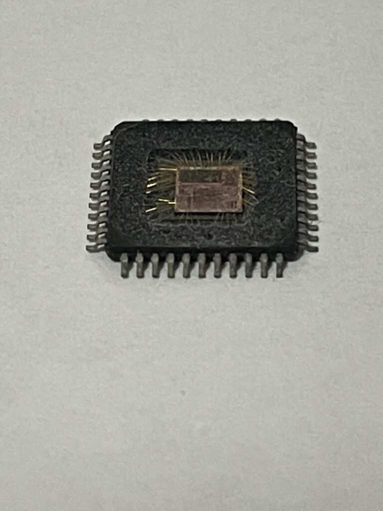
Crack NXP Microprocessor SPC5601DF1MLH4 Flash Memory
Crack NXP Microprocessor SPC5601DF1MLH4 Flash Memory and readout the embedded firmware including data and code from spc5601df1m MCU flash memory, and then copy binary file to new microcomputer;

All pads have a fixed configuration under reset.
During the power-up phase, all pads are forced to tristate.
After power-up phase, all pads are forced to tristate with the following exceptions:
PA[9] (FAB) is pull-down. Without external strong pull-up the device starts fetching from flash.
PA[8] (ABS[0]) is pull-up.
RESET pad is driven low. This is pull-up only after PHASE2 reset completion.
JTAG pads (TCK, TMS and TDI) are pull-up while TDO remains tristate.
Precise ADC pads (PB[7:4] and PD[11:0]) are left tristate (no output buffer available).
Main oscillator pads (EXTAL, XTAL) are tristate.
- Alternate functions are chosen by setting the values of the PCR.PA bitfields inside the SIUL module.
PCR.PA = 00 ® AF0; PCR.PA = 01 ® AF1; PCR.PA = 10 ® AF2; PCR.PA = 11 ® AF3. This is intended to select the output functions; to use one of the input functions, the PCR.IBE bit must be written to ‘1’, regardless of the values selected in the PCR in order to recover automobile microcontroller spc560p40l3 firmware from its locked flash memory.PA bitfields. For this reason, the value corresponding to an input only function is reported as “—”.

Multiple inputs are routed to all respective modules internally. The input of some modules must be configured by setting the values of the PSMIO.PADSELx bitfields inside the SIUL module.
All WKPU pins also support external interrupt capability. See “wakeup unit” chapter of the device reference manual for further details.
NMI has higher priority than alternate function. When NMI is selected, the PCR.AF field is ignored in the process of unlocking spc560p34l3 microcontroller flash memory binary.
5 “Not applicable” because these functions are available only while the device is booting. Refer to “BAM” chapter of the device reference manual for details.

