Crack MCU ATtiny261V Heximal
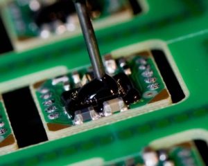
Crack MCU ATtiny261V and extract its content from memory like flash and eeprom, program and data will be integrated and dump out together, the microcontroller ATtiny261V can be read only when the status reset to unlocked one;
The ATtiny261V AVR is supported with a full suite of program and system development tools including: C Compilers, Macro Assemblers, Program Debugger/Simulators, In-Circuit Emulators, and Evaluation kits.
Port A is an 8-bit bi-directional I/O port with internal pull-up resistors (selected for each bit). The Port A output buffers have symmetrical drive characteristics with both high sink and source capability.
As inputs, Port A pins that are externally pulled low will source current if the pull-up resistors are activated. The Port A pins are tri-stated when a reset condition becomes active, even if the clock is not running.
Port B is an 8-bit bi-directional I/O port with internal pull-up resistors (selected for each bit). The Port B output buffers have symmetrical drive characteristics with both high sink and source capability.
As inputs, Port B pins that are externally pulled low will source current if the pull-up resistors are activated. The Port B pins are tri-stated when a reset condition becomes active, even if the clock is not running to faciliate MCU reading.
Reset input. A low level on this pin for longer than the minimum pulse length will generate a reset, even if the clock is not running.
1. For compatibility with future devices, reserved bits should be written to zero if accessed. Reserved I/O memory addresses should never be written.
2. I/O Registers within the address range 0x00 – 0x1F are directly bit-accessible using the SBI and CBI instructions. In these registers, the value of single bits can be checked by using the SBIS and SBIC instructions.
3. Some of the Status Flags are cleared by writing a logical one to them. Note that, unlike most other AVRs, the CBI and SBI instructions will only operation the specified bit, and can therefore be used on registers containing such Status Flags. The CBI and SBI instructions work with registers 0x00 to 0x1F only.
Tags: crack mcu encrypted bin,crack mcu encrypted code,crack mcu encrypted content,crack mcu encrypted data,crack mcu encrypted eeprom,crack mcu encrypted file,crack mcu encrypted firmware,crack mcu encrypted hexi,crack mcu encrypted information,crack mcu encrypted memory,crack mcu encrypted program


