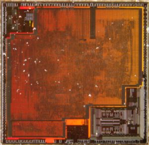
Copy DSP Controller TMS32F240PQA Memory Program
The TMS32F240PQA software-programmable interrupt structure supports flexible on-chip and external interrupt configurations to meet real-time interrupt-driven application requirements for Copy DSP Controller TMS32F240PQA Memory Program. The ’x240 recognizes three types of interrupt sources:
Reset (hardware- or software-initiated) is unarbitrated by the CPU and takes immediate priority over any other executing functions. All maskable interrupts are disabled until the reset service routine enables them.
Hardware-generated interrupts are requested by external pins or by on-chip peripherals.

Copy DSP Controller TMS32F240PQA Memory Program
There are two types:
– External interrupts are generated by one of five external pins corresponding to the interrupts XINT1, XINT2, XINT3, PDPINT, and NMI. The first four can be masked both by dedicated enable bits and by the CPU’s interrupt mask register (IMR), which can mask each maskable interrupt line at the DSP core. NMI, which is not maskable, takes priority over peripheral interrupts and software-generated interrupts. It can be locked out only by an already executing NMI or a reset.
– Peripheral interrupts are initiated internally by these on-chip peripheral modules: the event manager, SPI, SCI, watchdog/ real-time interrupt (WD/RTI), and ADC. They can be masked both by enable bits for each event in each peripheral and by the CPU’s IMR, which can mask each maskable interrupt line at the DSP core.
device reset and interrupts (continued)
Software-generated interrupts for the ’x240 device include:
– The INTR instruction. This instruction allows initialization of any ’x240 interrupt with software. Its operand indicates to which interrupt vector location the CPU branches. This instruction globally disables maskable interrupts (sets the INTM bit to 1).
– The NMI instruction. This instruction forces a branch to interrupt vector location 24h, the same location used for the nonmaskable hardware interrupt NMI. NMI can be initiated by driving the NMI pin low or by executing an NMI instruction. This instruction globally disables maskable interrupts on Copy DSP Controller TMS32F240PQA Memory Program.
– The TRAP instruction. This instruction forces the CPU to branch to interrupt vector location 22h. The TRAP instruction does not disable maskable interrupts (INTM is not set to 1); therefore, when the CPU branches to the interrupt service routine, that routine can be interrupted by the maskable hardware interrupts.
– An emulator trap. This interrupt can be generated with either an INTR instruction or a TRAP instruction.
reset
The reset operation ensures an orderly startup sequence for the device. There are five possible causes of a reset, as shown in below Figure. Three of these causes are internally generated; the other two causes, the RS and PORESET pins, are controlled externally.

